Abstract
Course overview: this course systematically explains the fundamentals of the overhead contact system (OCS) of electrified railways. Taking 112 teaching slides as its backbone, it covers four modules: basic structure, constituent equipment, suspension types and feeding methods. Starting from the overall supply circuit of the electric traction system, it dissects the four constituent parts of the OCS, namely contact suspension, support device, positioning device, and masts and foundations, and then introduces in depth the working principles and technical parameters of the core components: phase-break insulators, sectioning insulators, messenger wires, contact wires, droppers, electrical connections, overlap joints, centre anchors, compensation devices and switch crossings. Finally it compares simple suspension with catenary suspension, compares uncompensated, semi-compensated and fully compensated catenary suspension, and sets out the application scenarios of the four feeding arrangements: direct feeding, direct feeding with return conductor, AT feeding and BT feeding. The course suits induction training for OCS workers, professional study by signalling and electrical trainees, and reference use by engineering and technical staff.
Keywords: OCS fundamentals; contact suspension; catenary suspension; compensation device; feeding method; AT feeding; phase-break insulator; sectioning insulator; overlap joint; centre anchor
— The 112 teaching slides that follow explain the fundamentals of the OCS systematically —
Cover
Course Contents
The course is divided into four parts:
- Part 1: basic structure of the OCS
- Part 2: composition of the OCS
- Part 3: suspension types of the OCS
- Part 4: feeding methods of the OCS
I. Basic Structure of the OCS
Related products: Bracket system · Positioning device · Support and positioning assembly
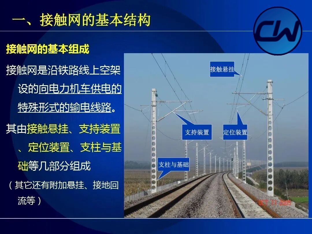
The OCS is a special form of transmission line erected above the railway track to supply electric locomotives. It consists of contact suspension, support device, positioning device, masts and foundations, together with additional suspension, earthing and return paths. This section begins with the overall structure of the electric traction system and then introduces the four basic parts of the OCS itself.
1.1 Composition of the electric traction system
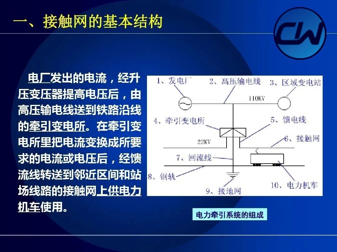
The current generated at the power station is raised in voltage by a step-up transformer and carried by a high-voltage transmission line (110 kV) to the traction substations along the railway. In the traction substation the current is converted to the required current or voltage (27.5 kV) and then transferred through the feeder to the OCS of the adjacent section and station tracks for use by the electric locomotive. The current used by the locomotive returns to the substation through the rails, the return conductor and the earthing network, forming a complete supply circuit.
1.2 Basic composition of the OCS
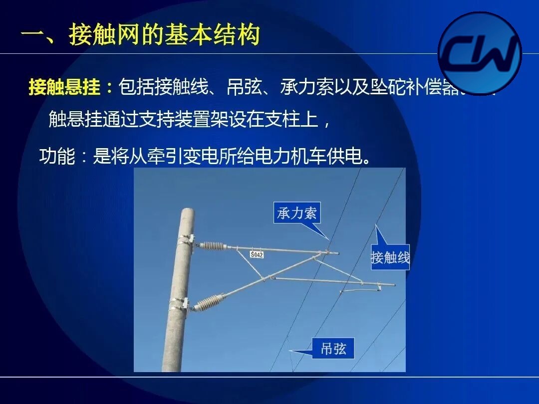
The OCS is a special form of transmission line erected above the railway track to supply electric locomotives. It consists of contact suspension, support device, positioning device, masts and foundations, together with additional suspension, earthing and return paths.
1.3 Positioning device
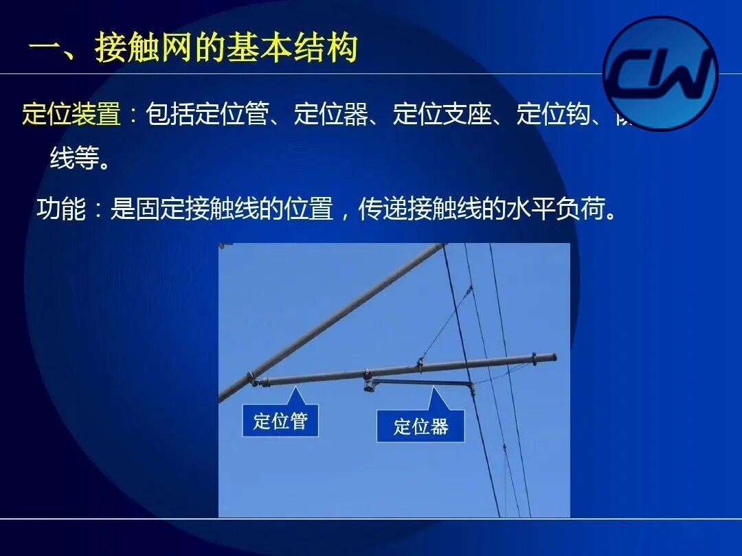
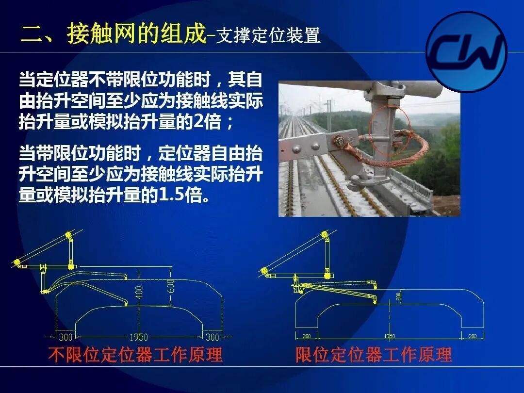
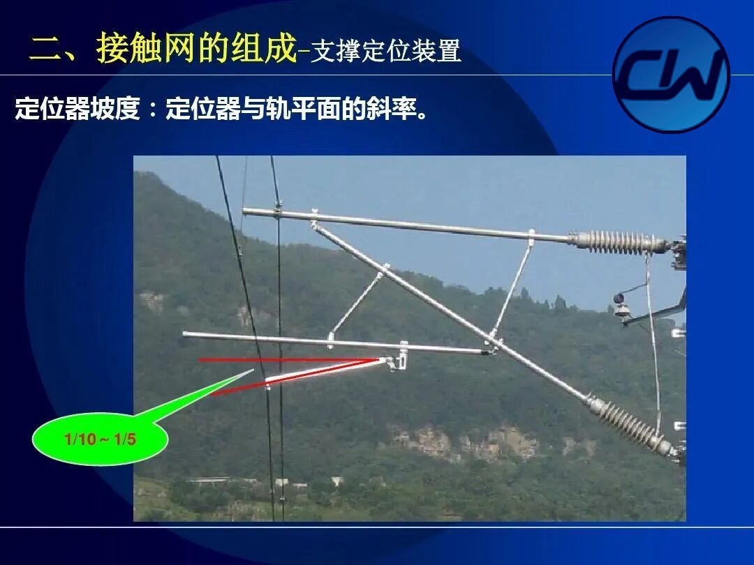
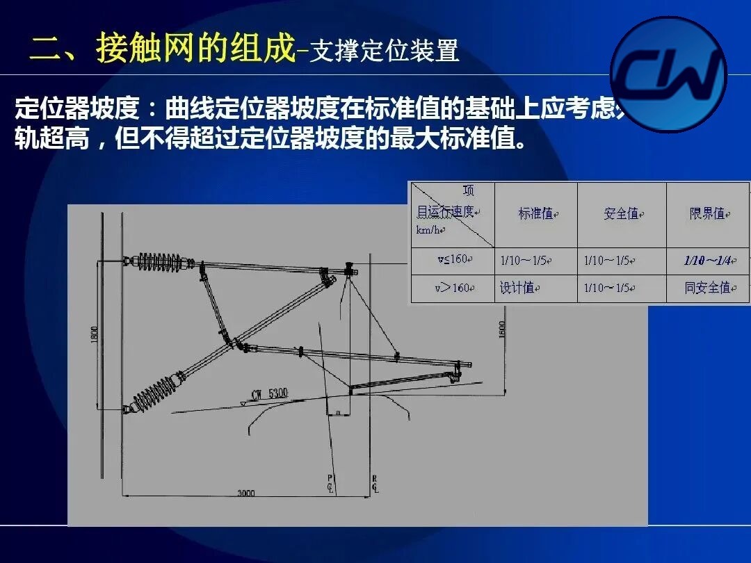
The positioning device comprises the positioning tube, the steady arm, the positioning bracket, the positioning hook and the positioning clamp. Its function is to fix the position of the contact wire, transmit the horizontal load of the contact wire and keep the wire within the running envelope of the pantograph contact strip. The positioning device is normally mounted on the cantilever of the mast and insulated from the mast by insulators.
1.4 Support device
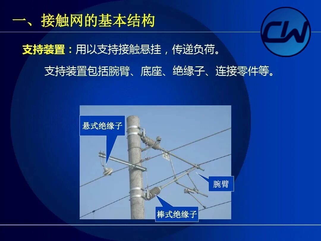
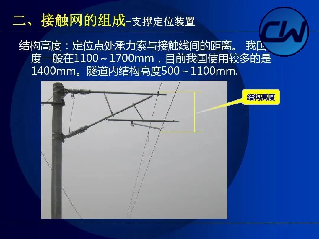
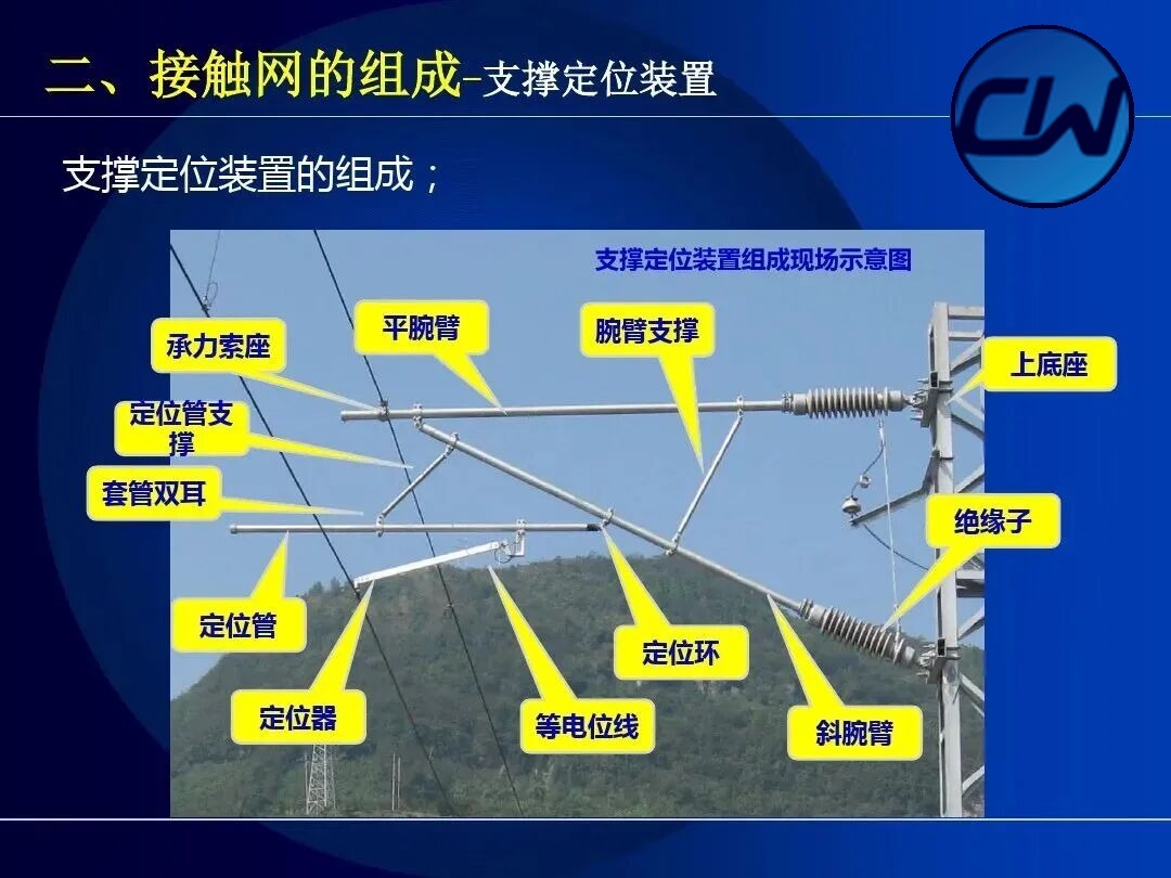
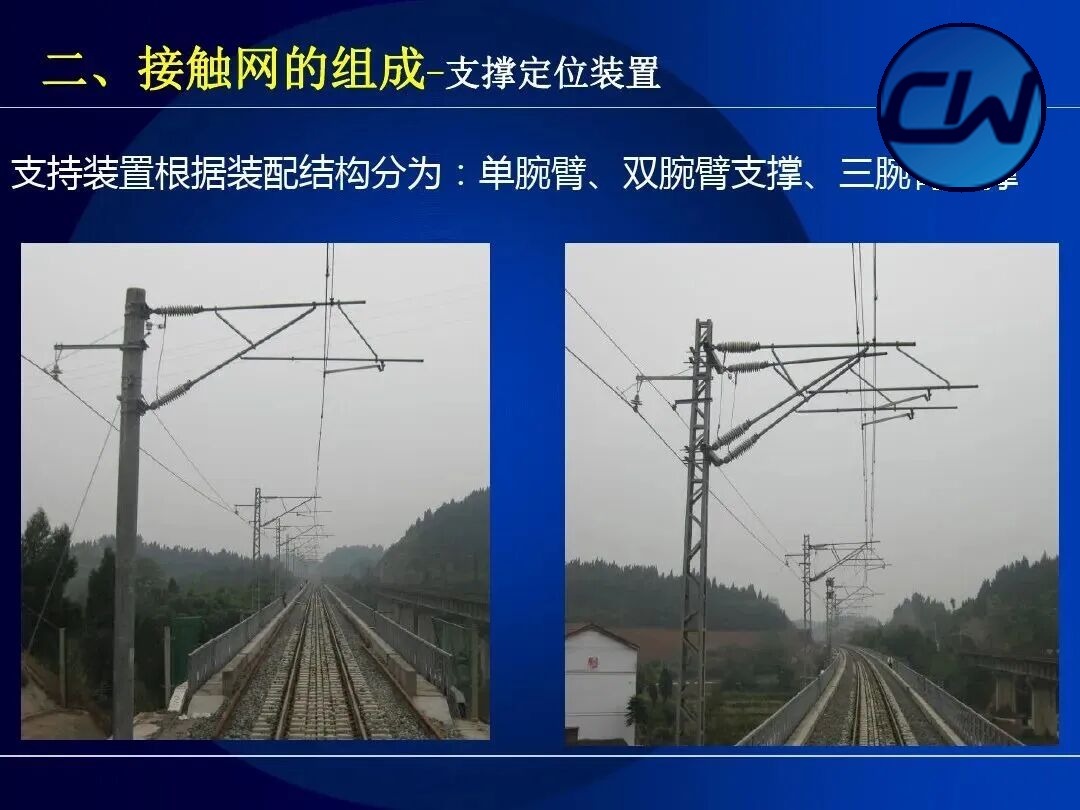
The support device carries the contact suspension and transmits the load. It comprises the cantilever, base, insulators and connecting parts. According to its assembly the support device is classified as single cantilever, double cantilever support or triple cantilever support, and each form serves a different track layout.
II. Composition of the OCS
Related products: Phase-break insulator · Sectioning insulator · Insulators · Contact suspension · Compensation device · Electrical connection · Centre anchor · Switch crossing · Connection fasteners · Masts and foundations
This part is the core of the course and explains in detail the working principles, technical parameters and field application of each constituent part of the OCS. It covers equipment (phase-break insulators, sectioning insulators and insulators), contact suspension (messenger wire, contact wire, droppers, electrical connections, switch crossings, centre anchors, compensation devices and overlap joints), the support and positioning assembly, and masts and foundations.
2.1 Equipment
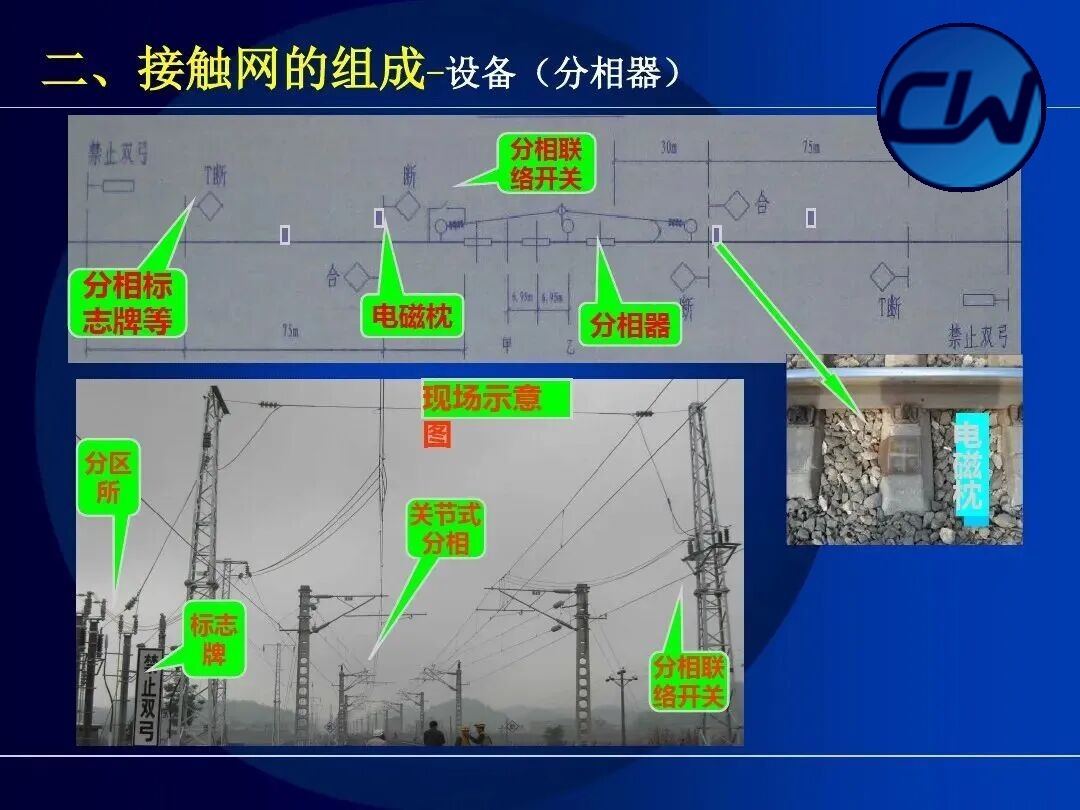
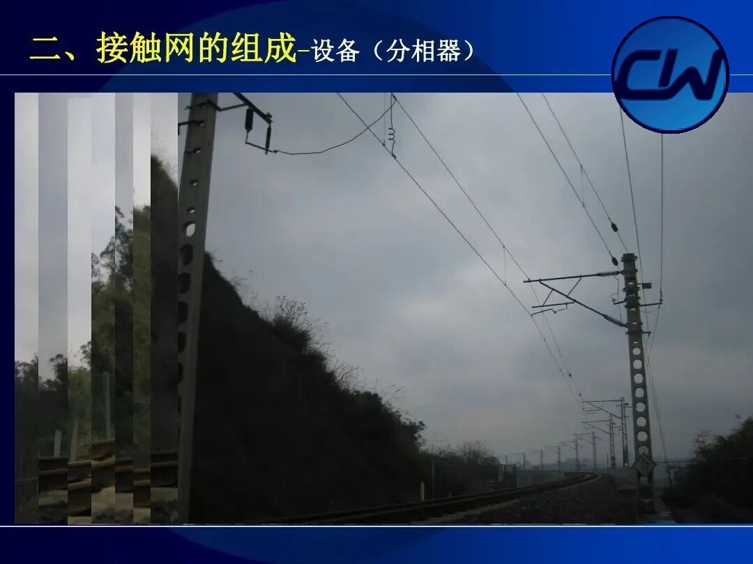
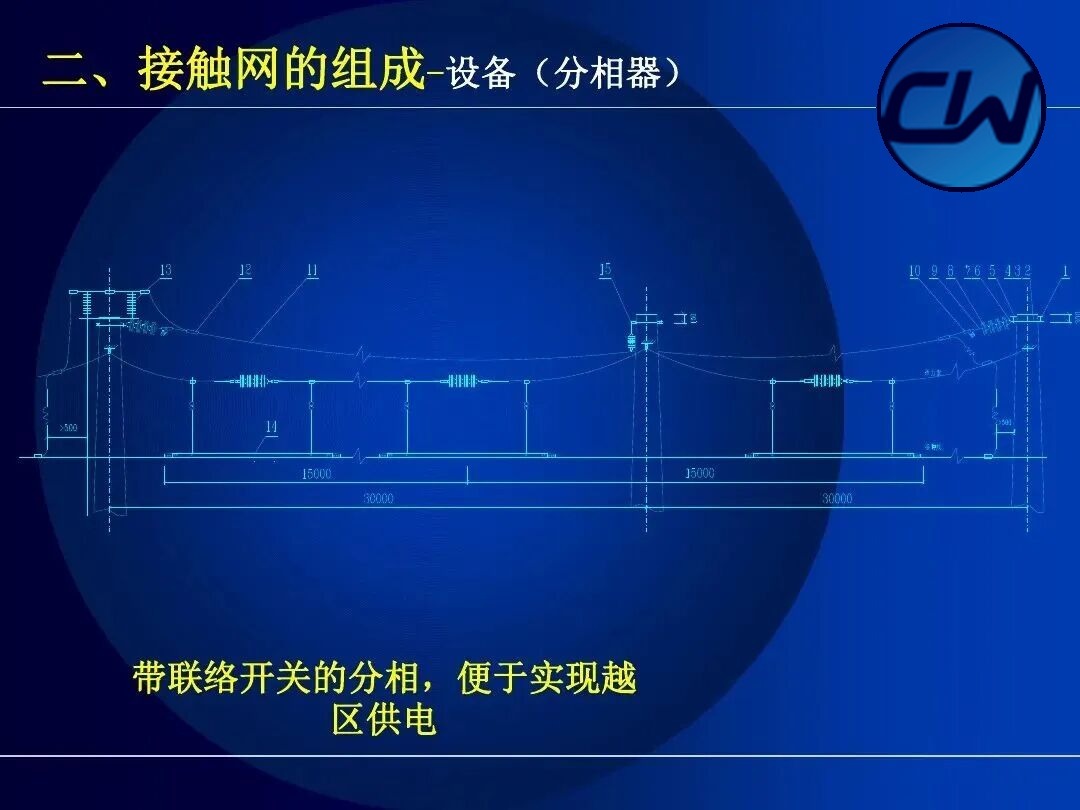
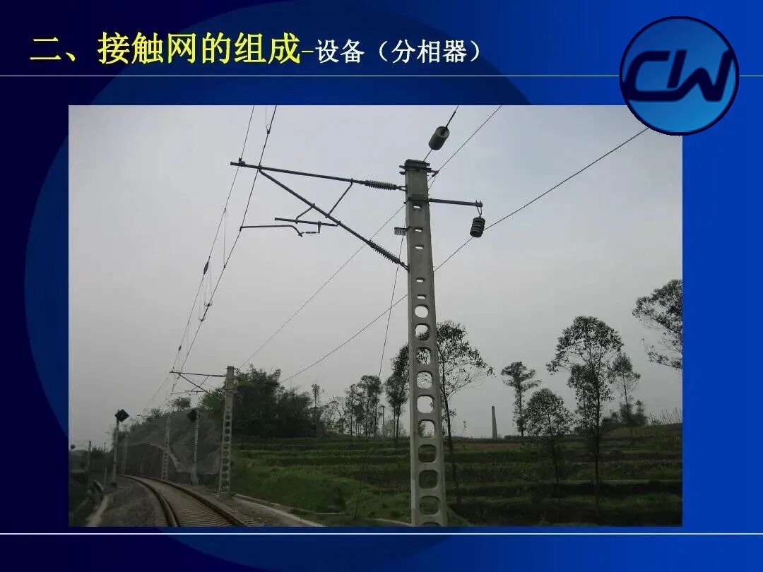
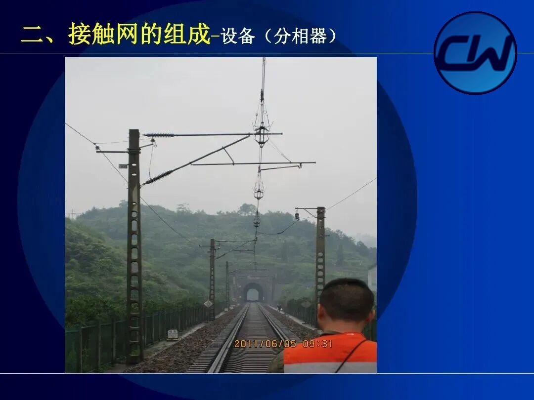
2.1.1 Phase-break insulator (phase splitter)
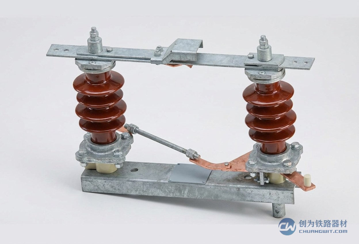
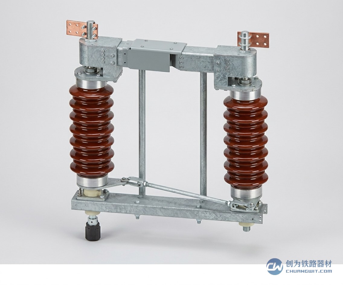
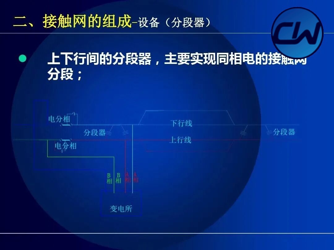
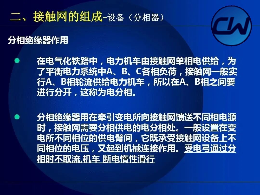
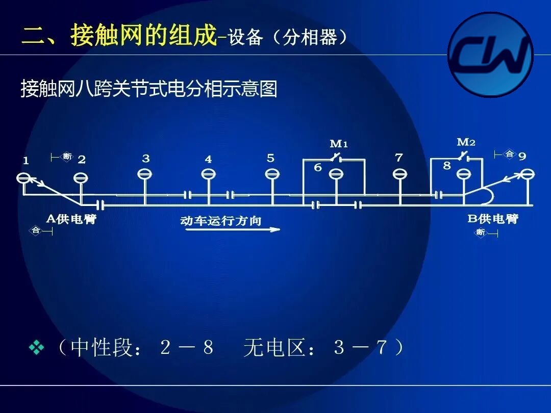
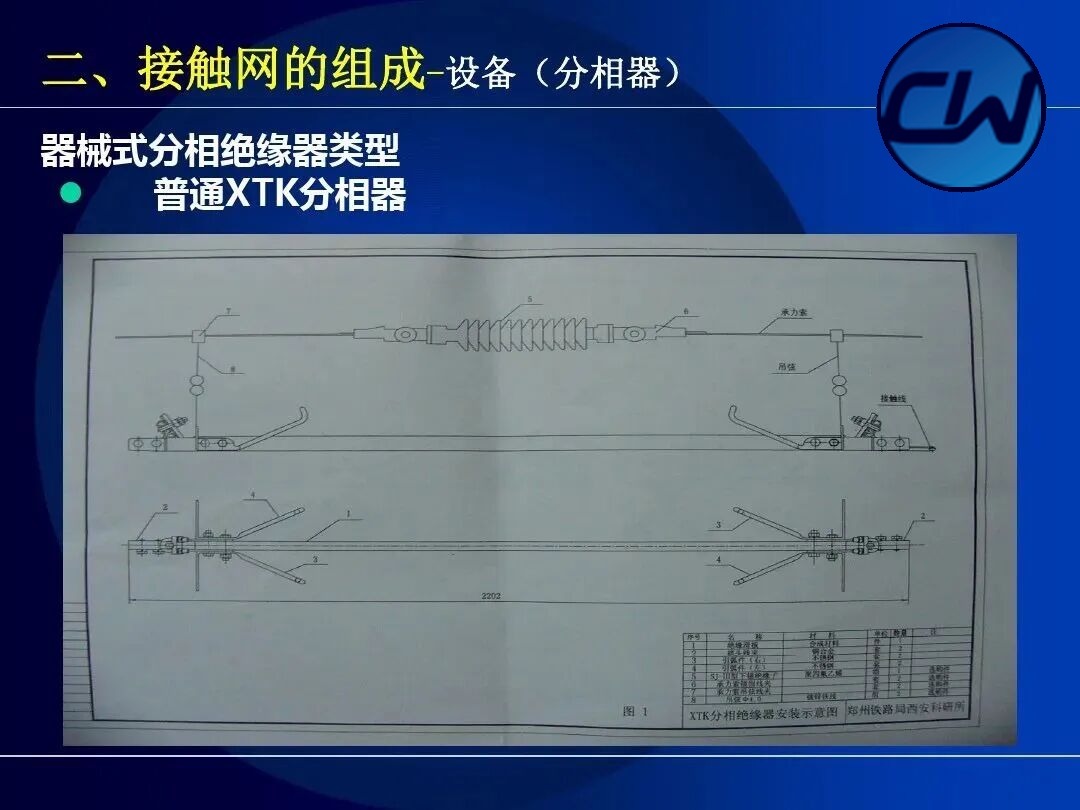
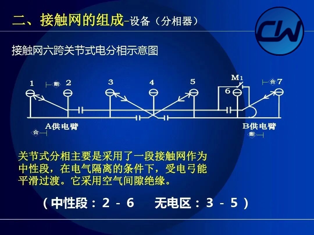
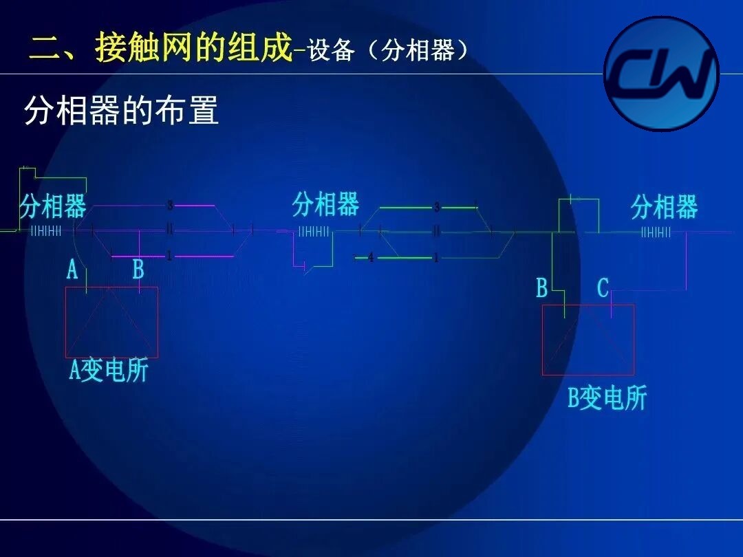
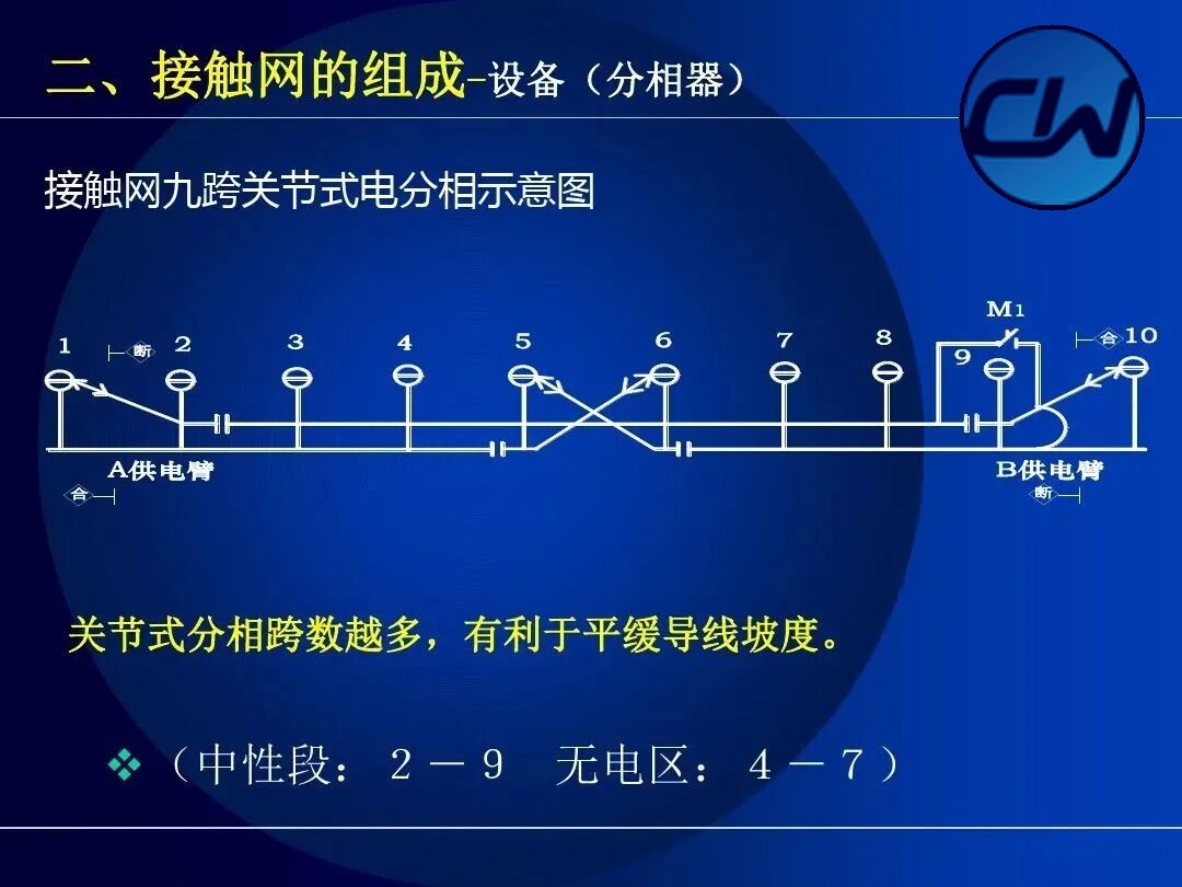
In an electrified railway the electric locomotive is supplied with single-phase power from the OCS. In order to balance the load of phases A, B and C in the power system, the OCS usually supplies locomotives from phases A and B alternately, so the two phases have to be separated from each other. This is called an electrical phase break. The phase-break insulator is used where the OCS has to be fed in separate phases, that is where the traction substation feeds different phases into the OCS. It is normally installed between feeding arms of different phase at the substation, and it both withstands the voltage difference between phases and provides a mechanical connection. The pantograph does not draw current while passing the phase break and the locomotive coasts through it with its breaker open.
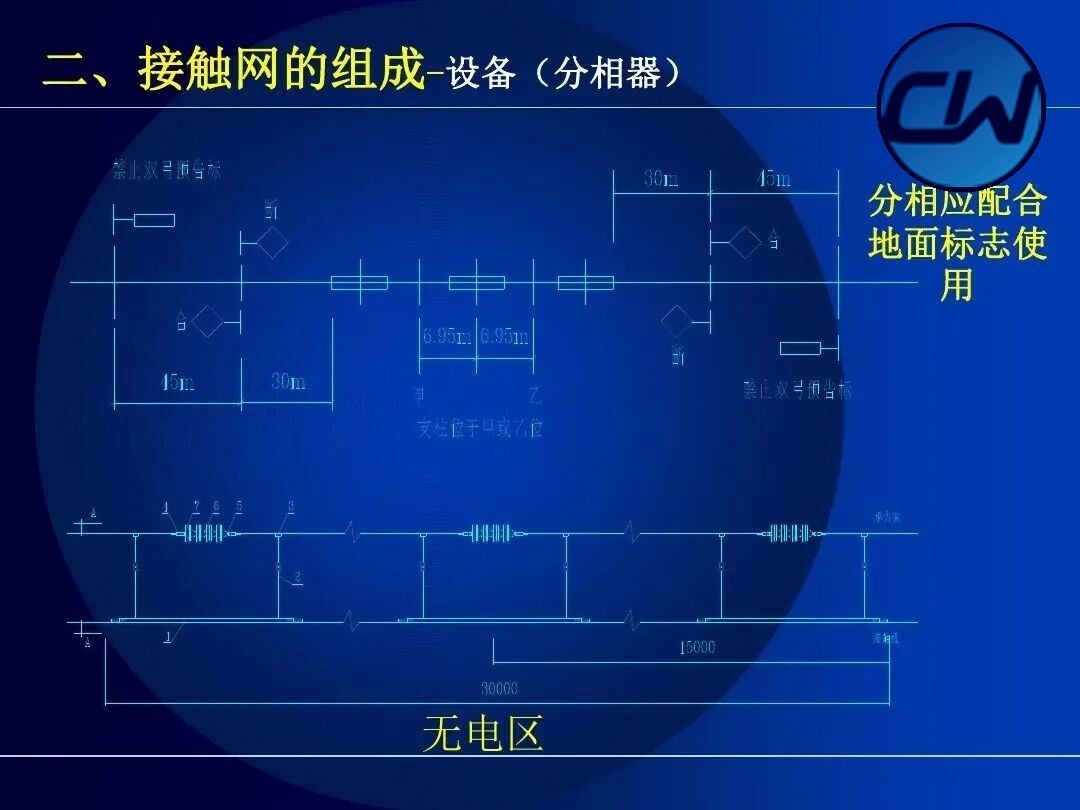
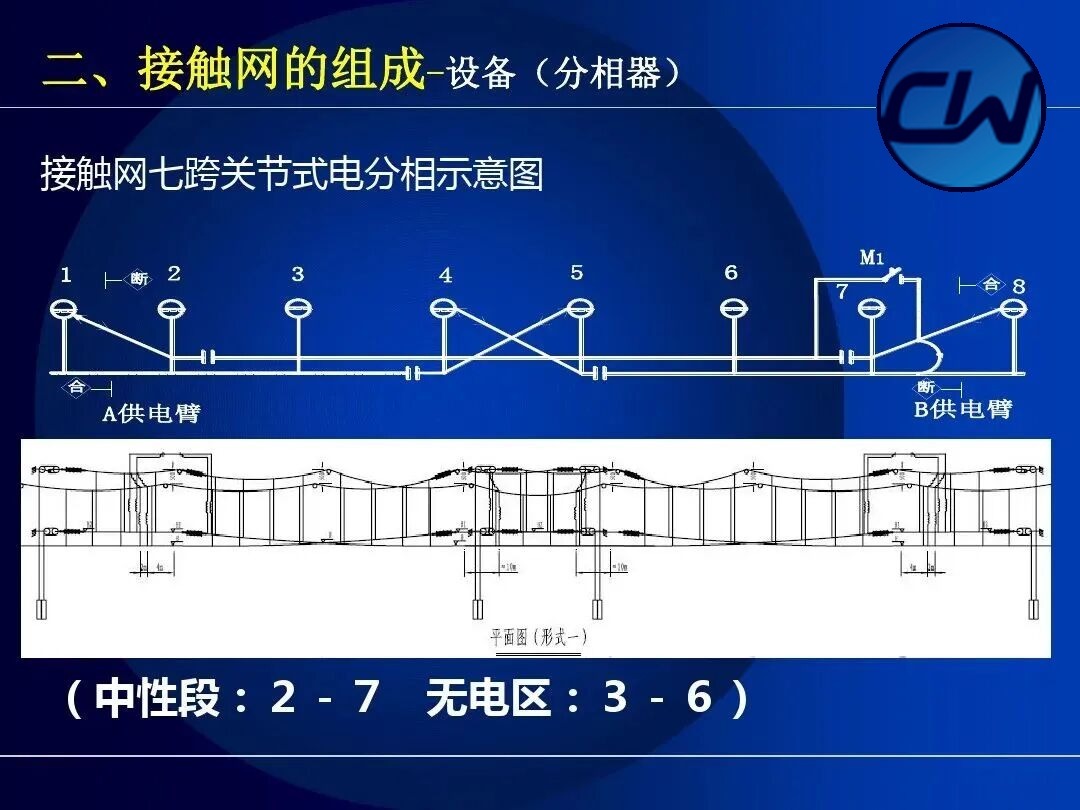
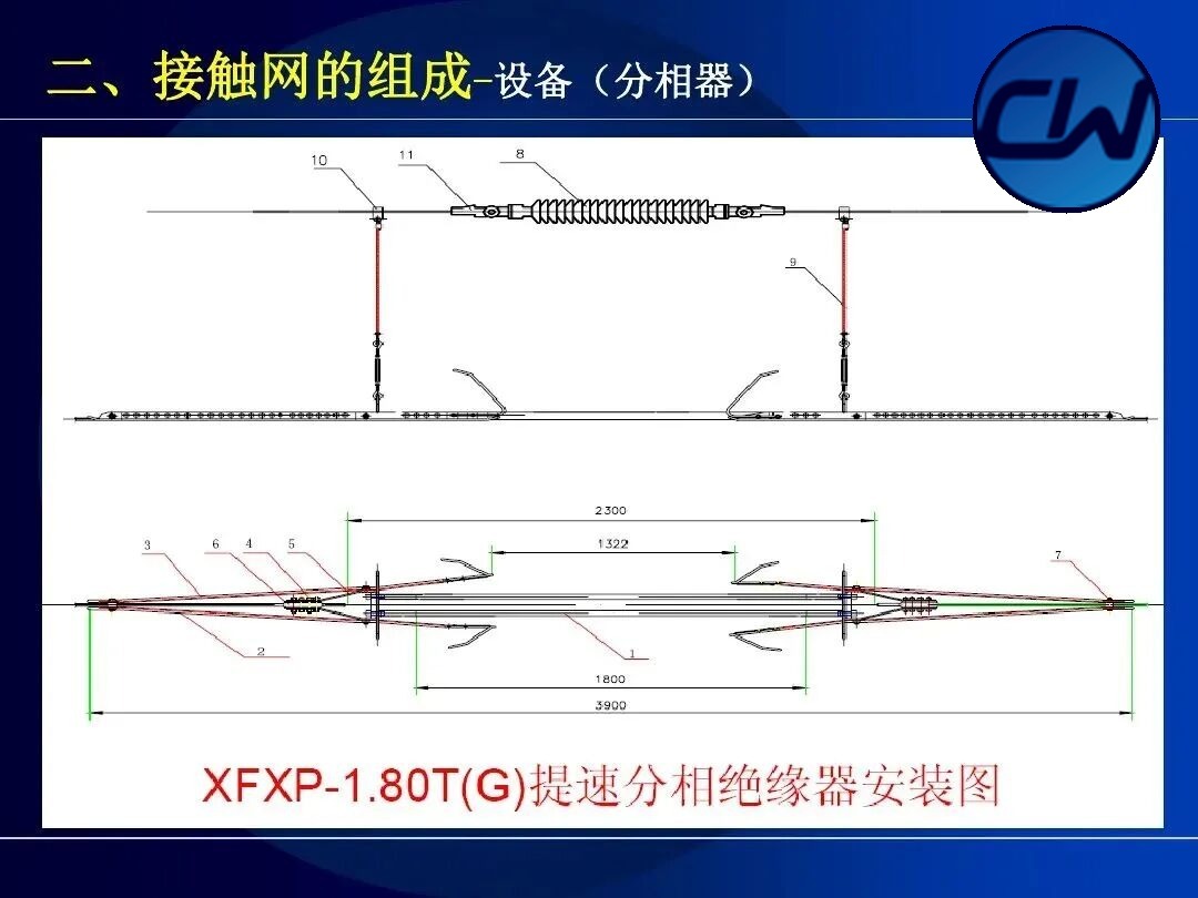
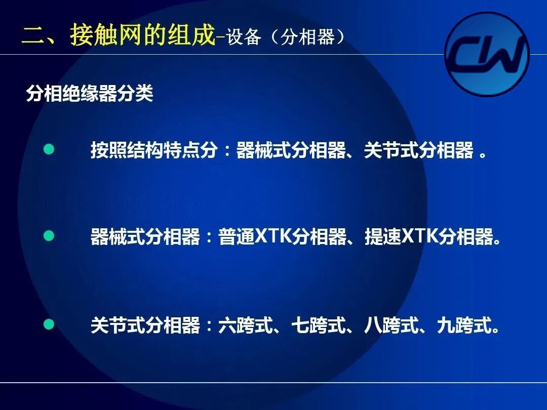
Phase breaks take several forms, including the seven-span, eight-span and nine-span arrangements. The commonest is the seven-span articulated phase break, made up of a neutral section (2-8 spans) and a dead section (3-7 spans). The XTK phase-break insulator is one of the common mechanical types.
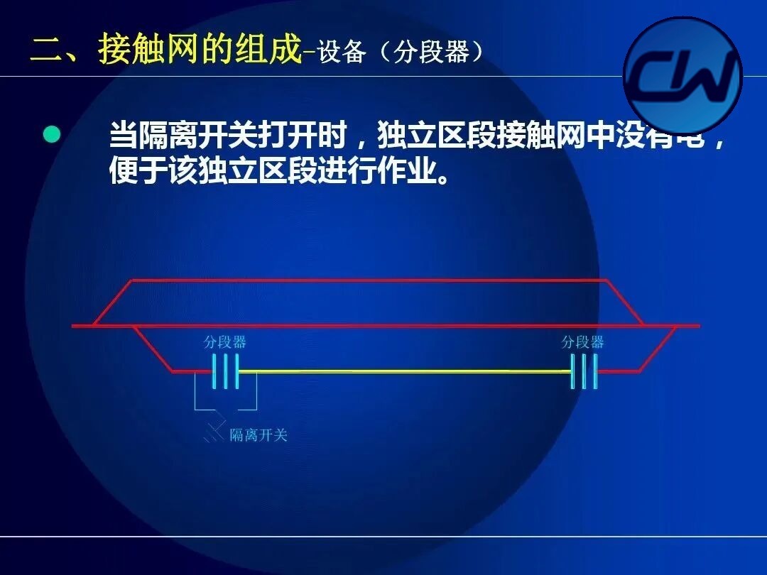
2.1.2 Sectioning insulator (section splitter)
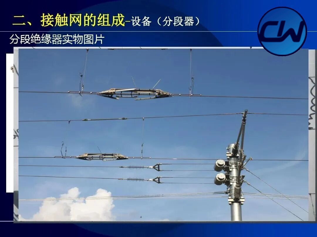
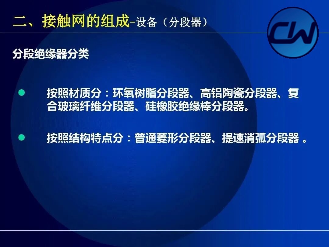
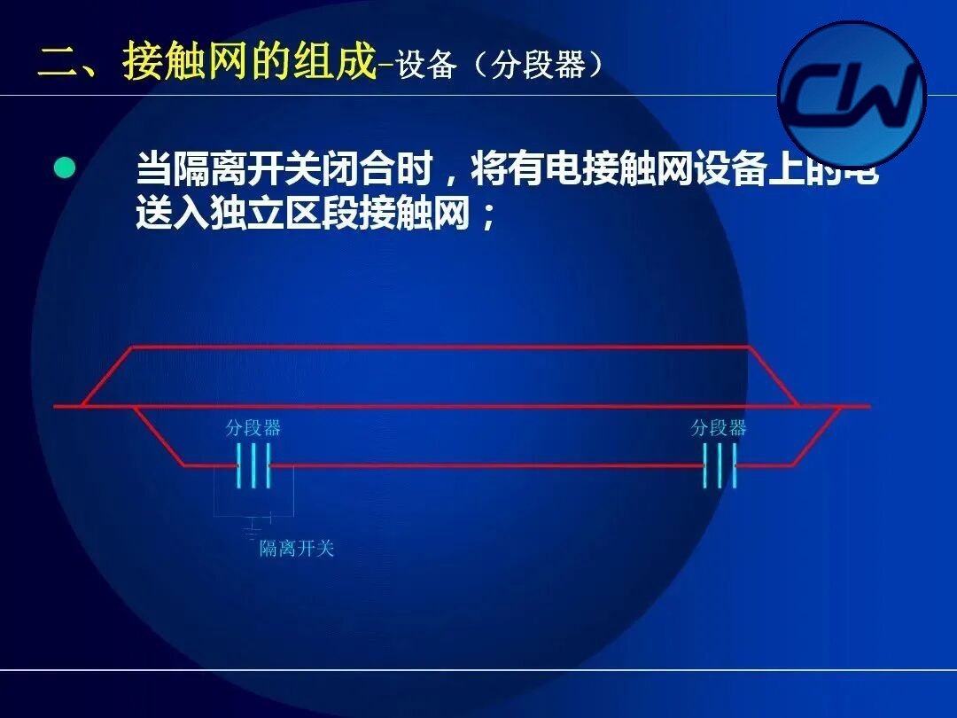
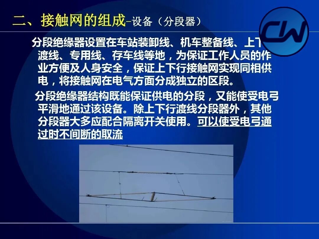
The sectioning insulator is used to section the OCS where the phase is the same, dividing the OCS electrically into independent sections so that maintenance is easier and the extent of an incident is limited. By material the sectioning insulator is classified as epoxy-resin, high-alumina ceramic, composite glass-fibre and silicone-rubber rod types; by structural feature as the ordinary diamond type and the speed-raising arc-suppressing type.
2.1.3 Insulators
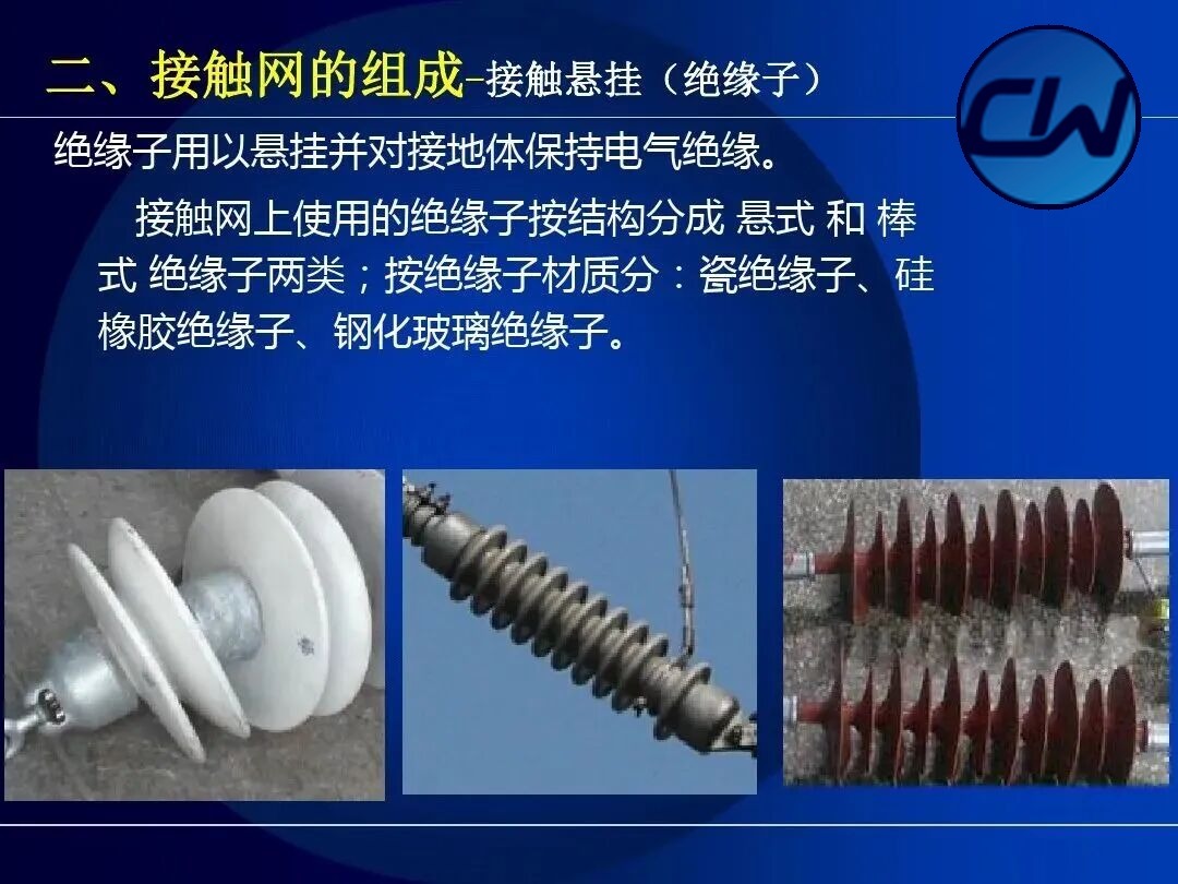
Insulators support the suspension and maintain electrical insulation from earthed structures. Insulators used on the OCS are divided by structure into the suspension type and the rod type; by material into porcelain, silicone-rubber and toughened-glass insulators.
2.2 Contact suspension
The contact suspension is the core of the OCS: it touches the pantograph of the electric locomotive directly and supplies the locomotive continuously. It is made up of the contact wire, the messenger wire, the droppers, the electrical connections, the switch crossings, the centre anchors, the compensation devices and the overlap joints.
2.2.1 Messenger wire
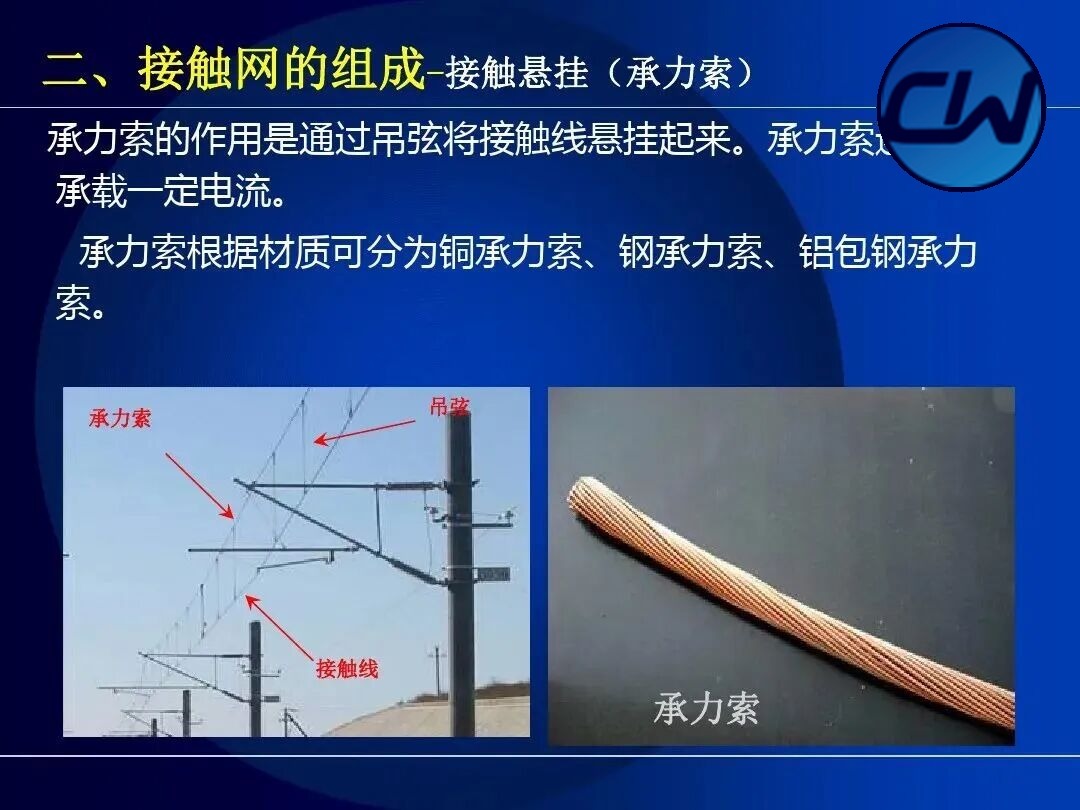
The function of the messenger wire is to suspend the contact wire through the droppers while carrying part of the current. By material the messenger wire is classified as copper, steel or aluminium-clad steel.
2.2.2 Contact wire
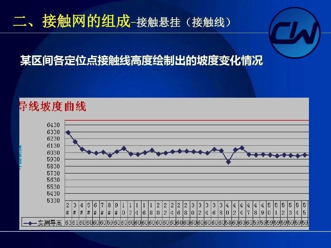
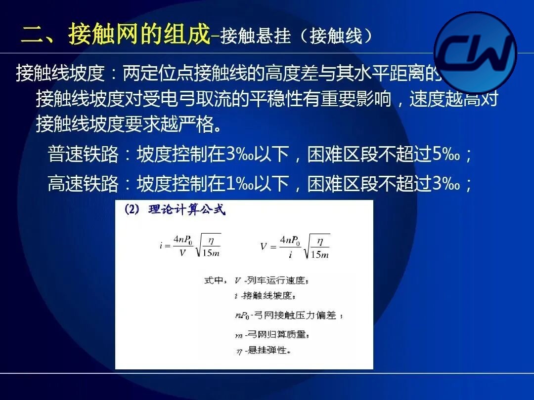
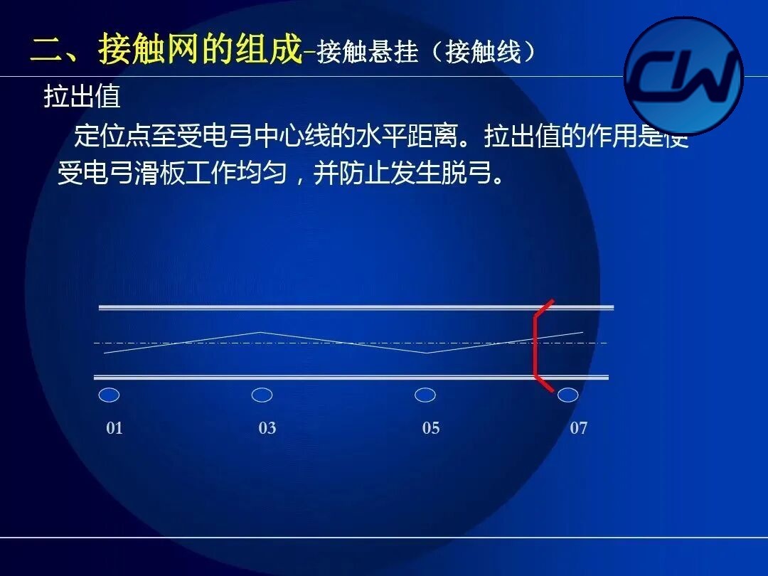
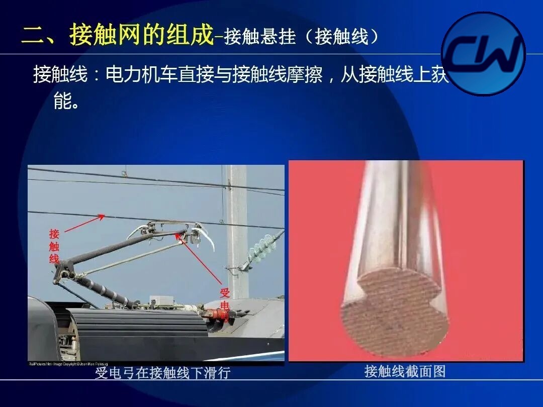
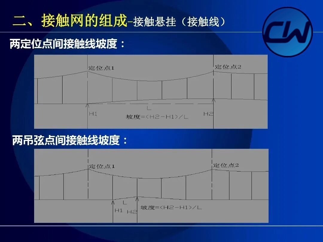
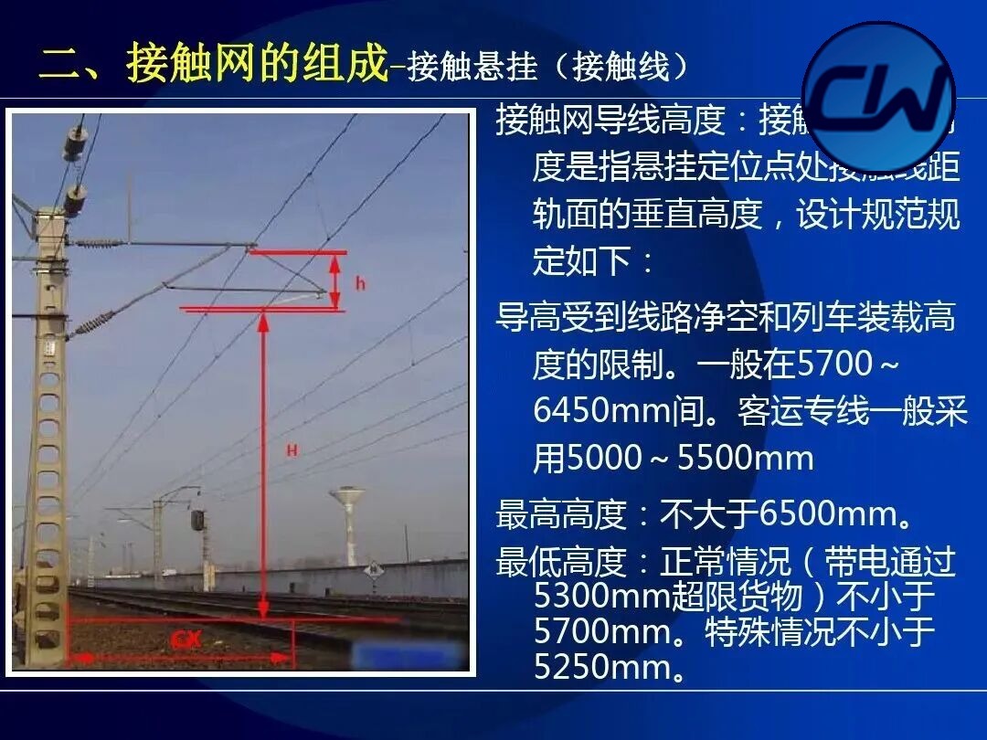
The contact wire is the conductor that the pantograph touches and rubs against. Its height, tension and gradient are all subject to strict requirements, and standard values are laid down for the gradient between two positioning points and between two dropper points.
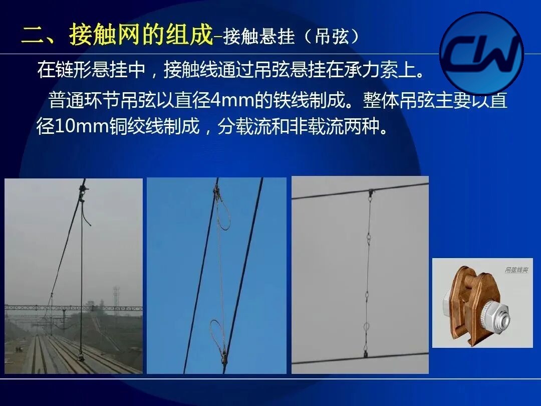
2.2.3 Droppers
The dropper is the intermediate component connecting the messenger wire and the contact wire; it carries the contact wire from the messenger wire. Droppers come in several types, including the link-type dropper, the elastic dropper and the pulley dropper.
2.2.4 Electrical connections
Electrical connections keep the current flowing freely between the conductors of the contact suspension. They comprise transverse and longitudinal connections and are the key component for continuity of the OCS circuit.
2.2.5 Overlap joints
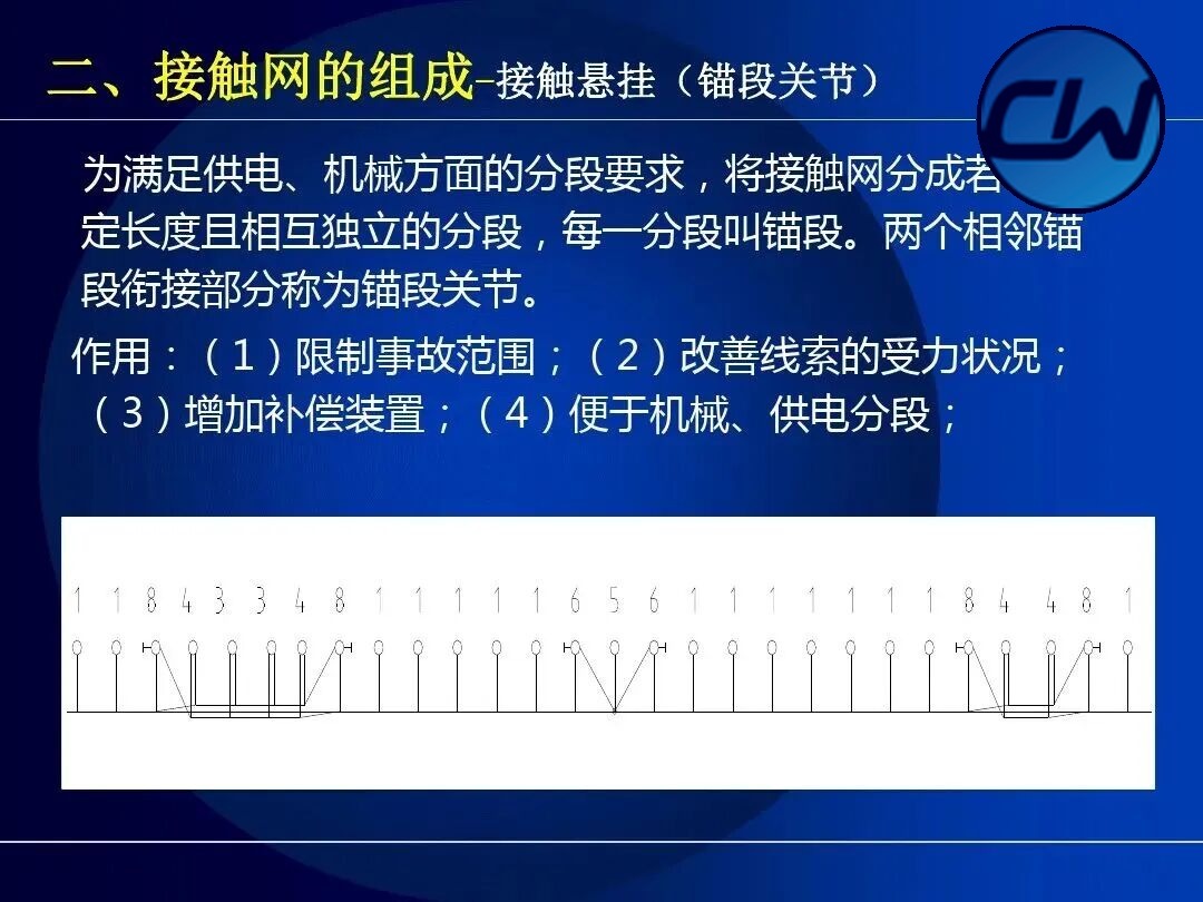
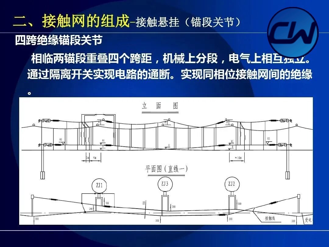
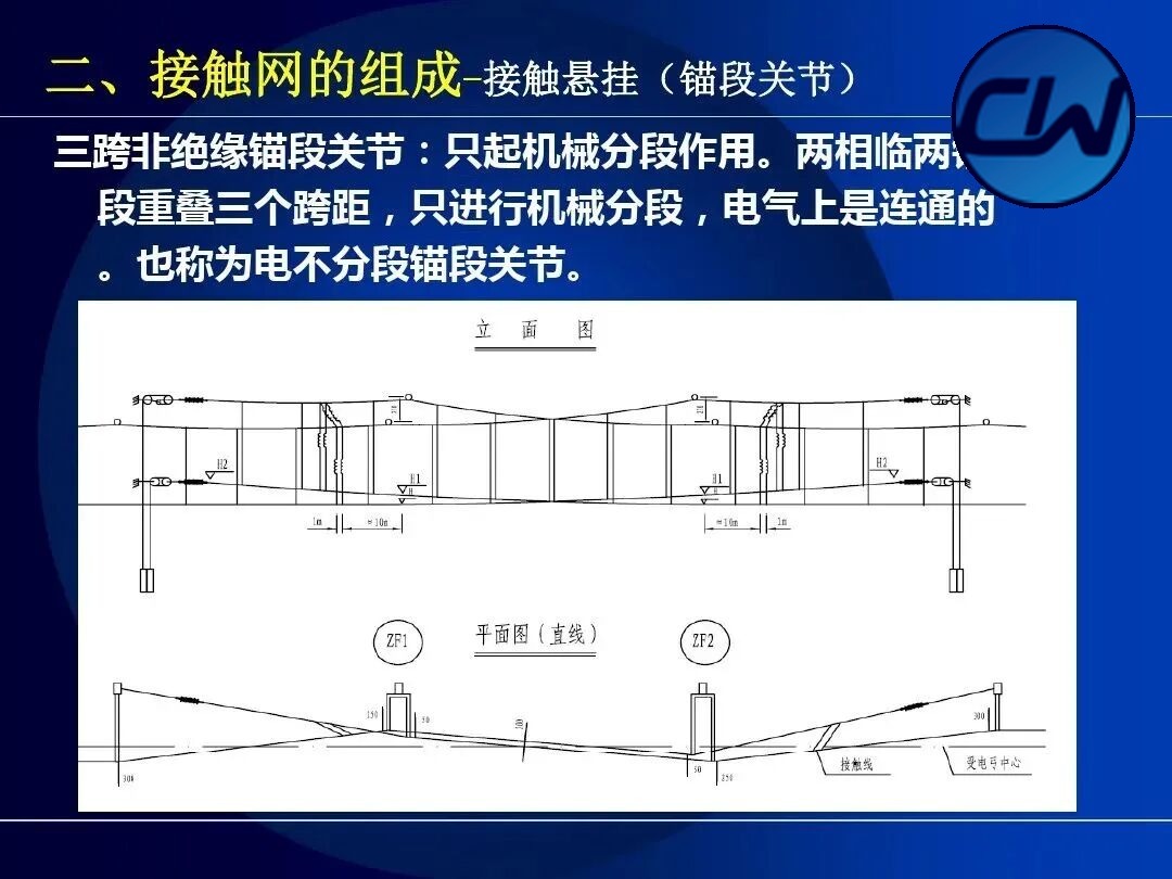
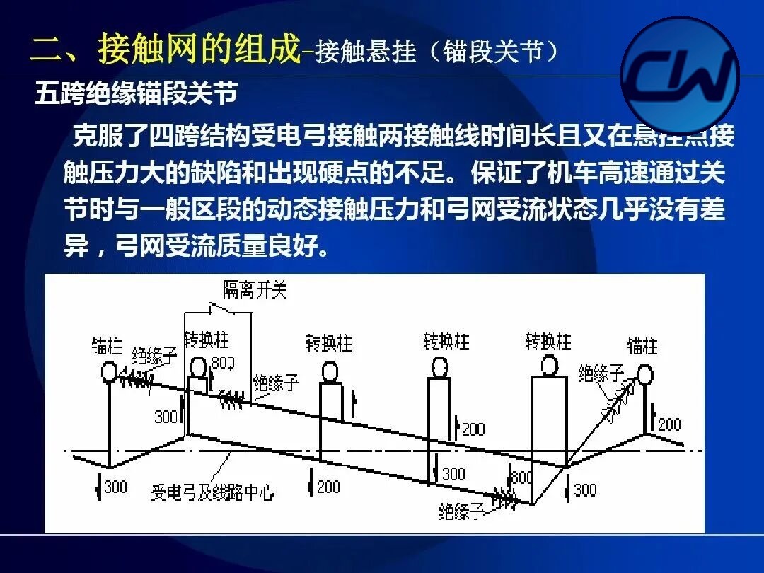
To meet the sectioning requirements of supply and mechanics, the OCS is divided into independent lengths, each of which is called an anchor section. The junction between two adjacent anchor sections is called an overlap joint. Its functions are: (1) to limit the extent of an incident; (2) to improve the stress state of the conductors; (3) to provide for compensation devices; and (4) to facilitate mechanical and electrical sectioning.
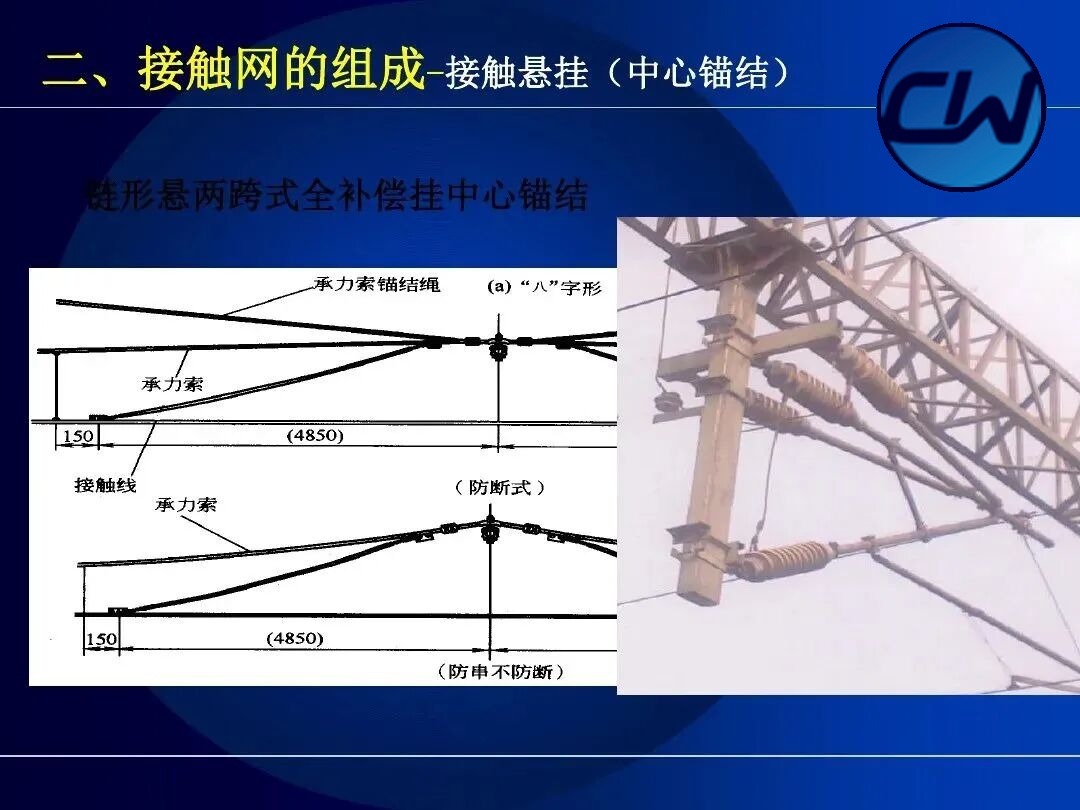
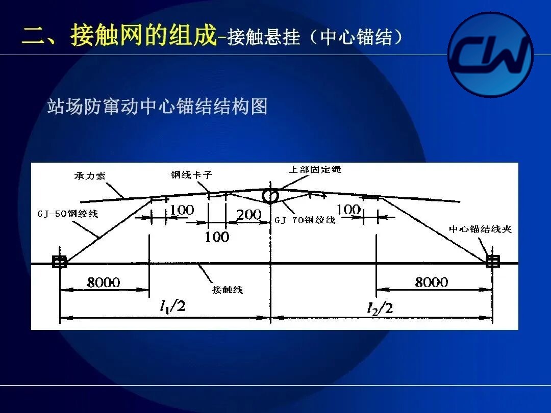
2.2.6 Centre anchor
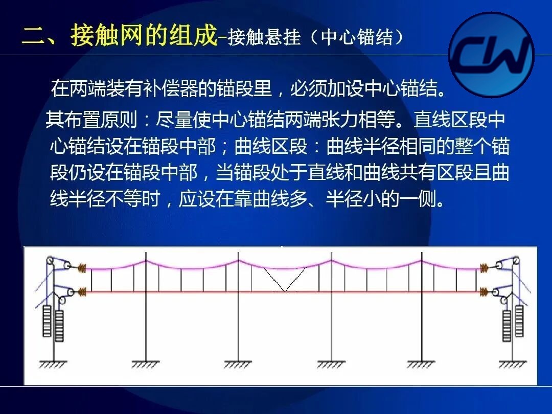
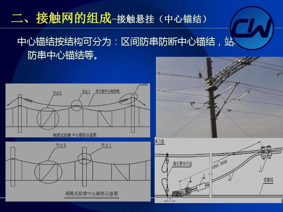
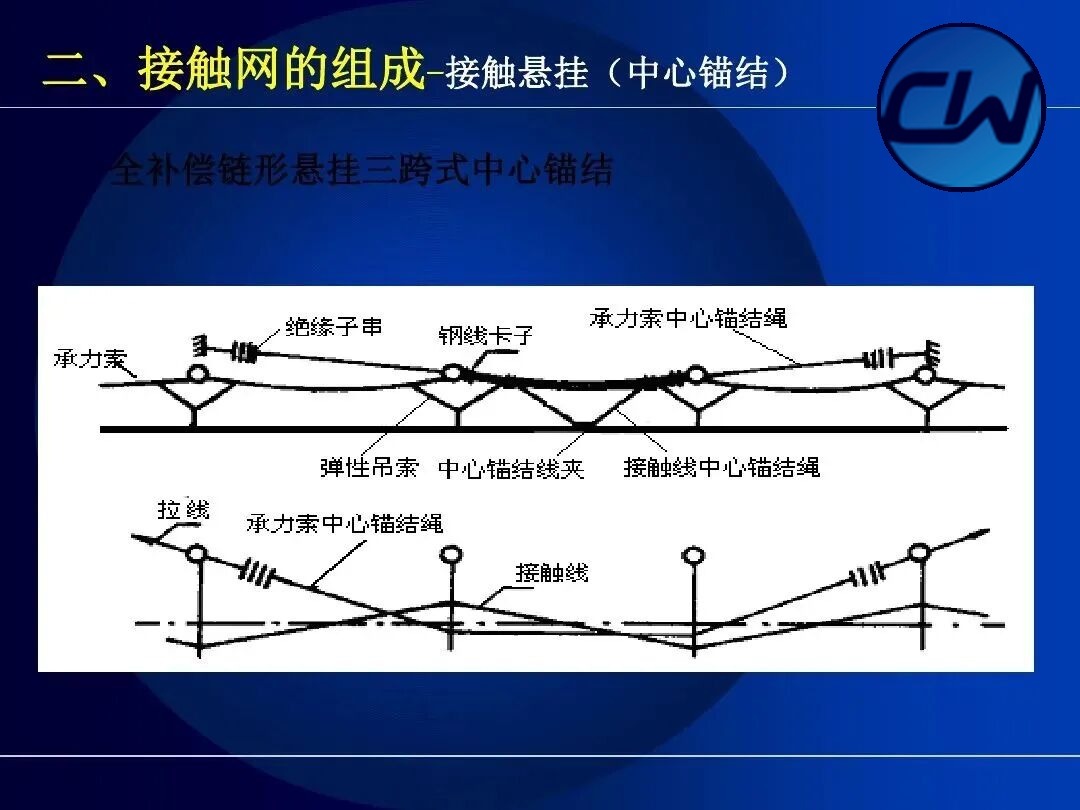
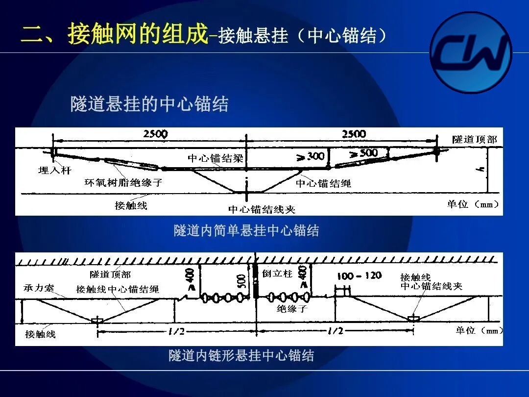
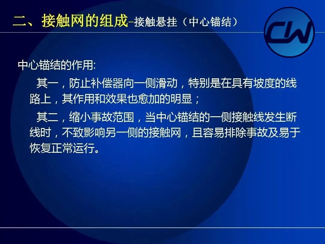
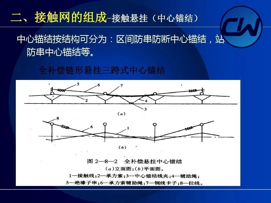
In an anchor section equipped with compensators at both ends, a centre anchor must be added. The arrangement principle is to make the tension at the two ends of the centre anchor as nearly equal as possible. On straight track the centre anchor is placed at the middle of the anchor section; on curved track it is placed at the middle of the whole anchor section of uniform radius. By structure the centre anchor is classified as the anti-creep anti-break type for open line and the anti-creep type for stations and yards.
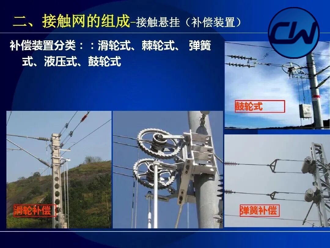
2.2.7 Compensation devices
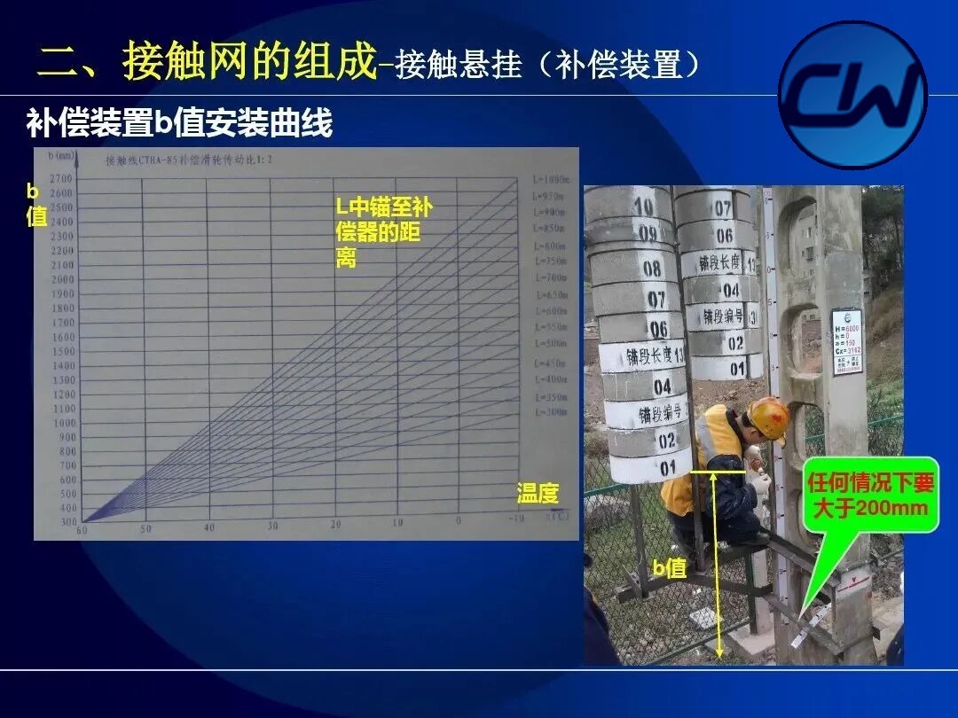
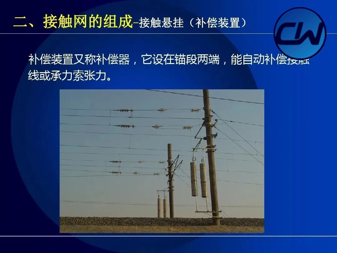
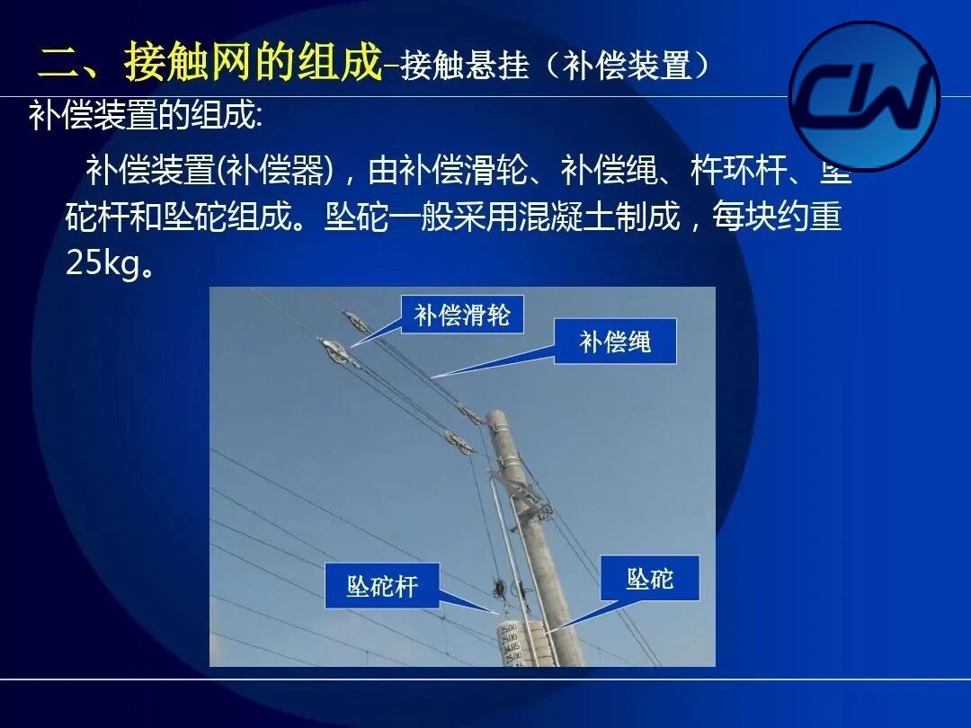
The compensation device adjusts the conductor tension automatically so that the tension of the contact wire or messenger wire stays within the specified range. Compensation devices are classified as pulley type, ratchet type, spring type, hydraulic type and drum type.
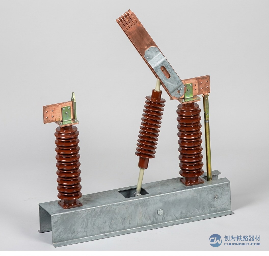
2.2.8 Switch crossings
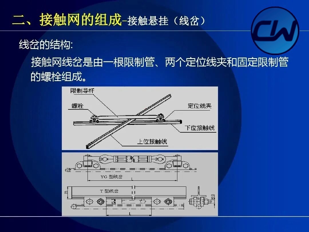
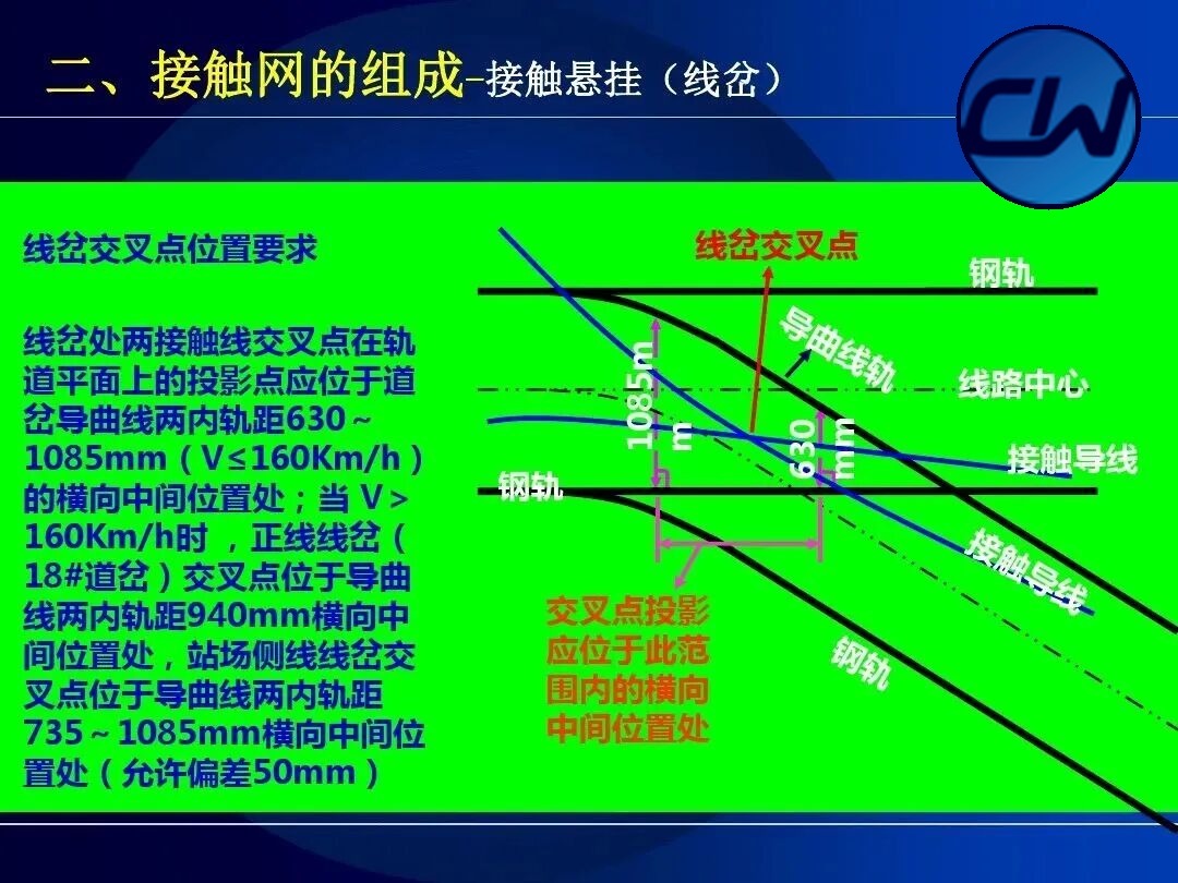
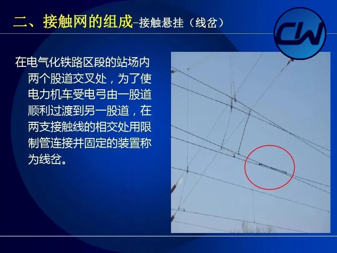
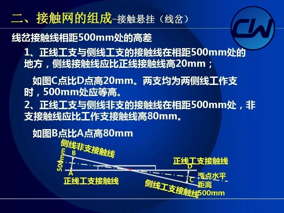
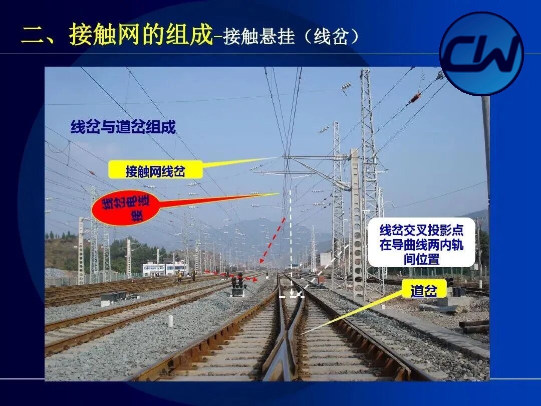
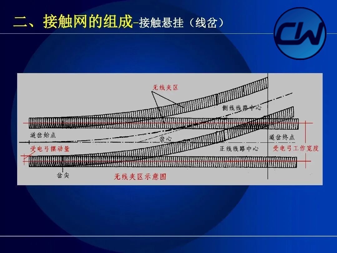
Where two tracks cross in the station yard of an electrified section, a switch crossing is the device that connects and fixes the two contact wires at their point of intersection with a limiting tube, so that the pantograph can pass smoothly from one track to the other. The projection of the crossing point of the two contact wires on the track plane must lie at the transverse middle of the two inner rail distances of 630~1085 mm (V ≤ 160 km/h) on the diverging curve of the turnout.
2.3 Support and positioning assembly
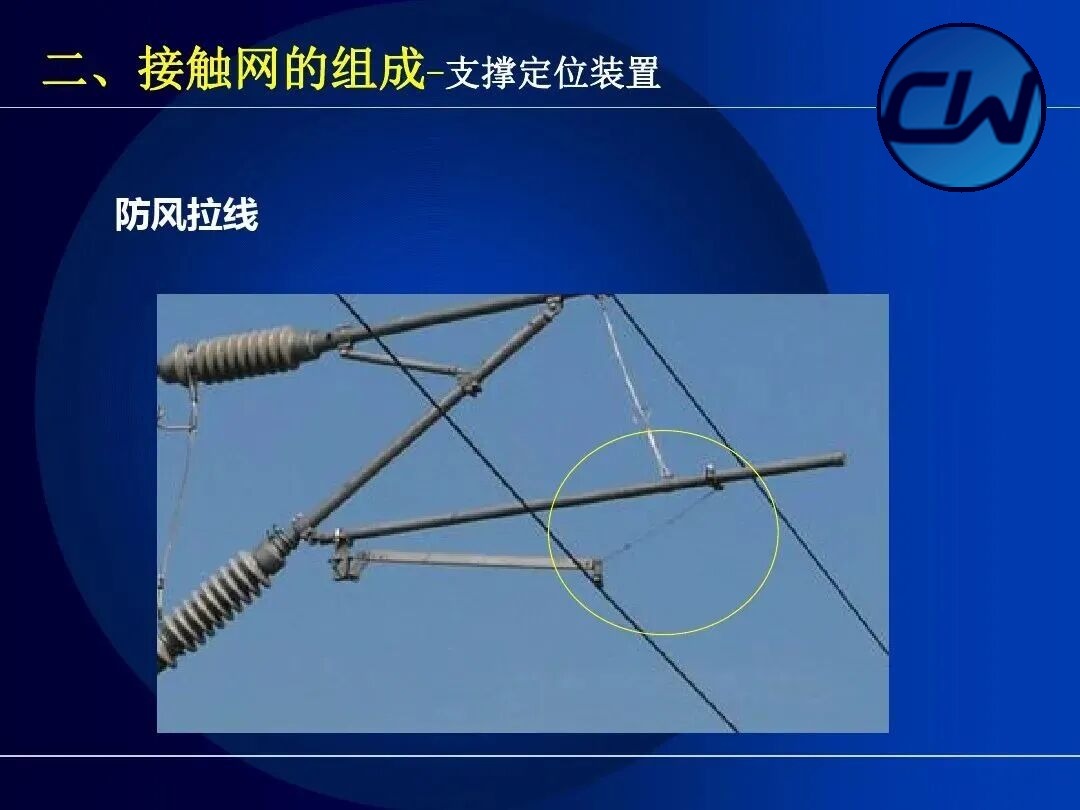
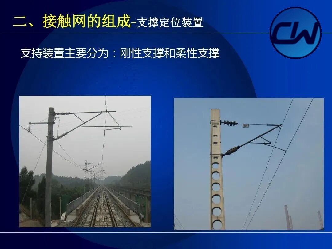
The support and positioning assembly is the mechanical structure of the OCS responsible for support and positioning; it comprises the cantilever, positioning tube, steady arm and insulators. By assembly it is classified as single cantilever, double cantilever support and triple cantilever support.
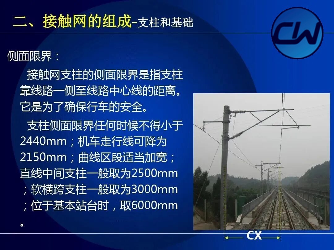
2.4 Masts and foundations
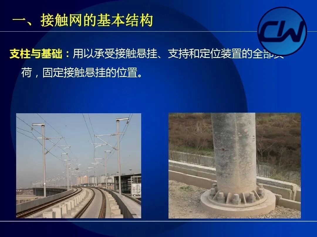
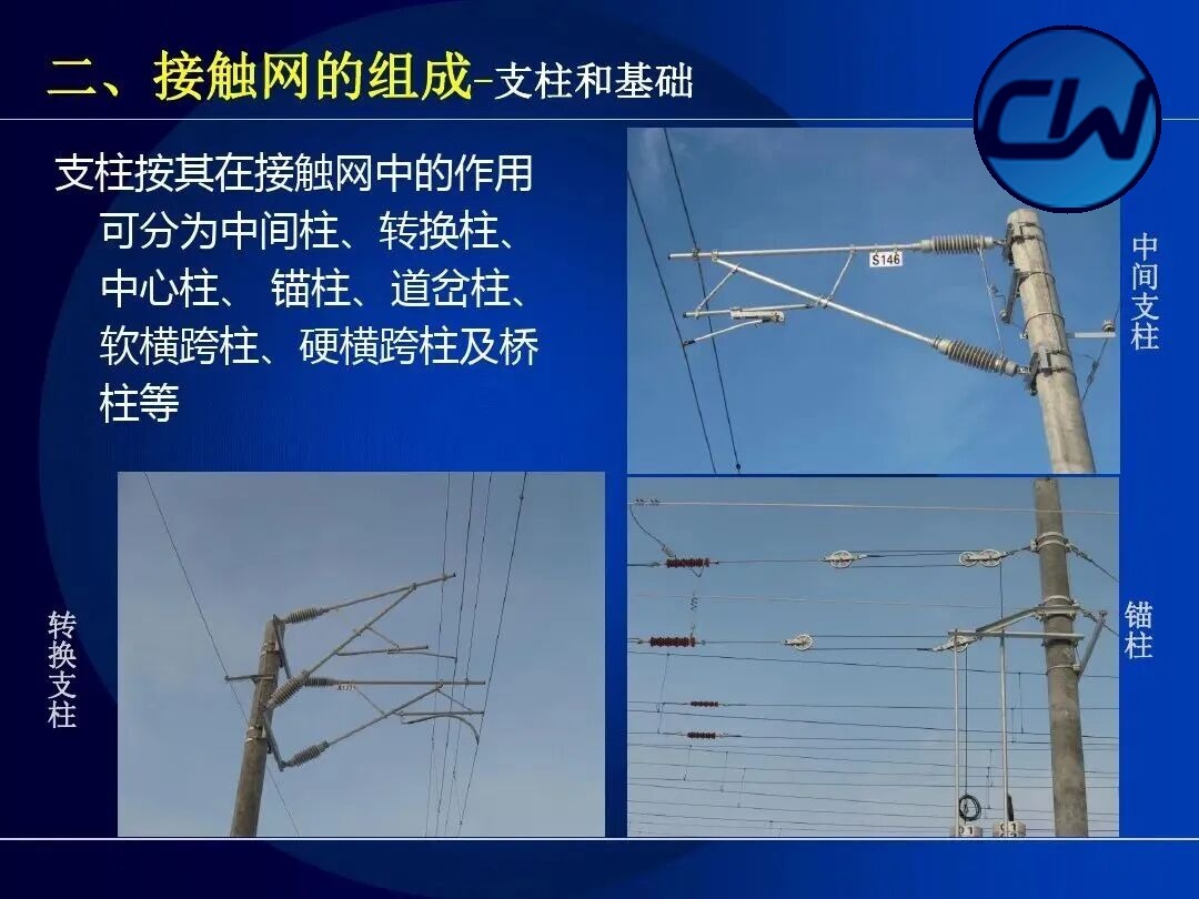
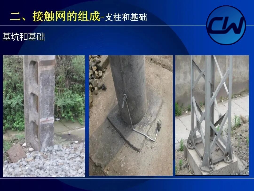
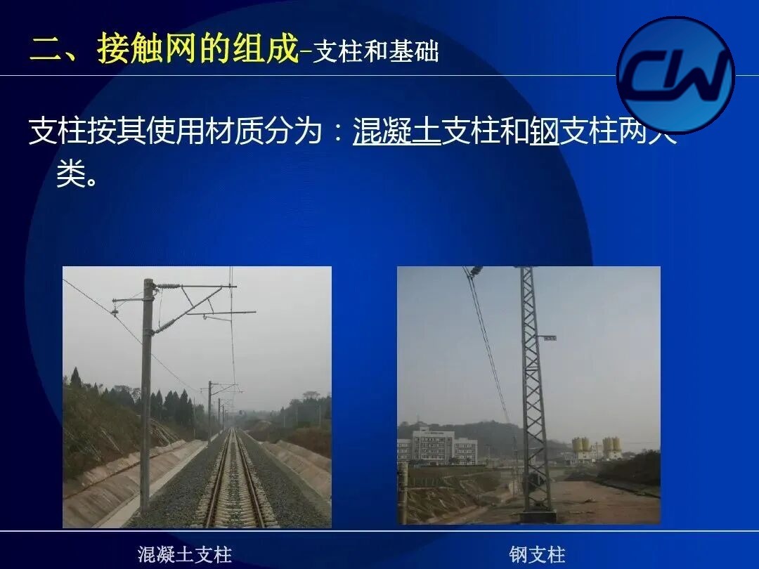
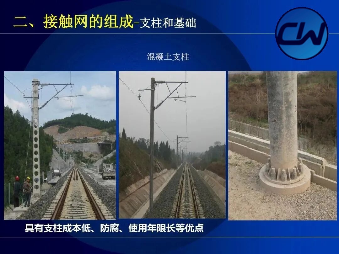
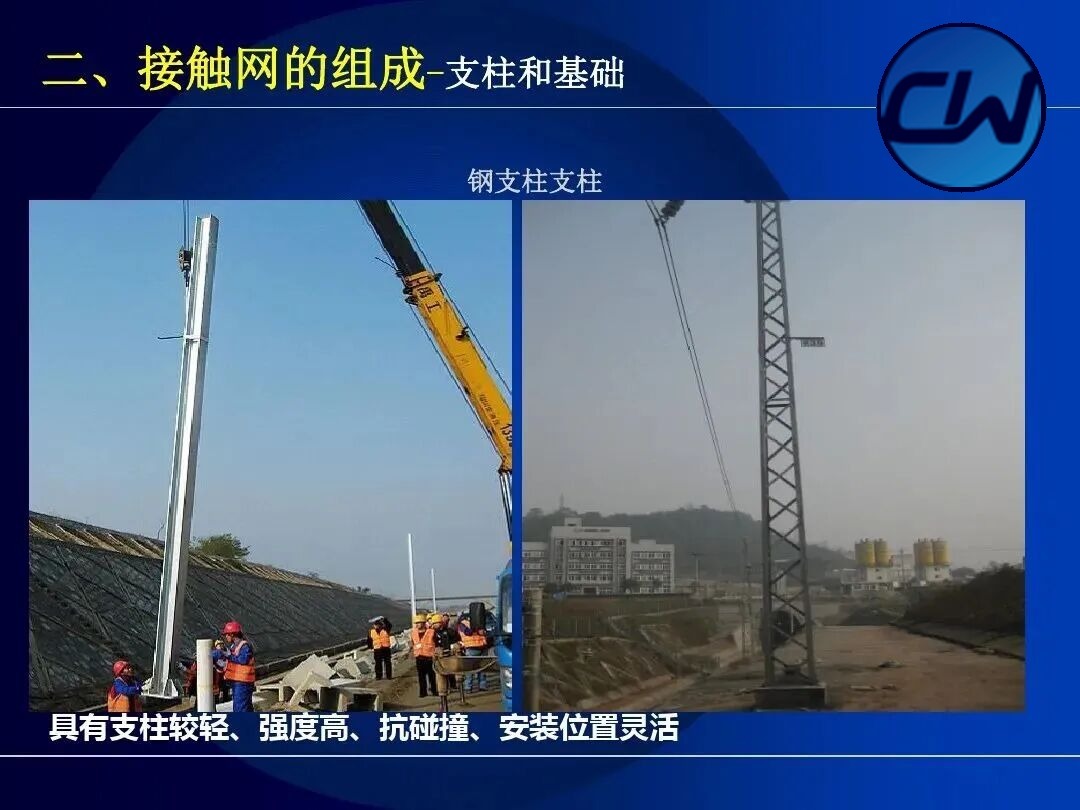
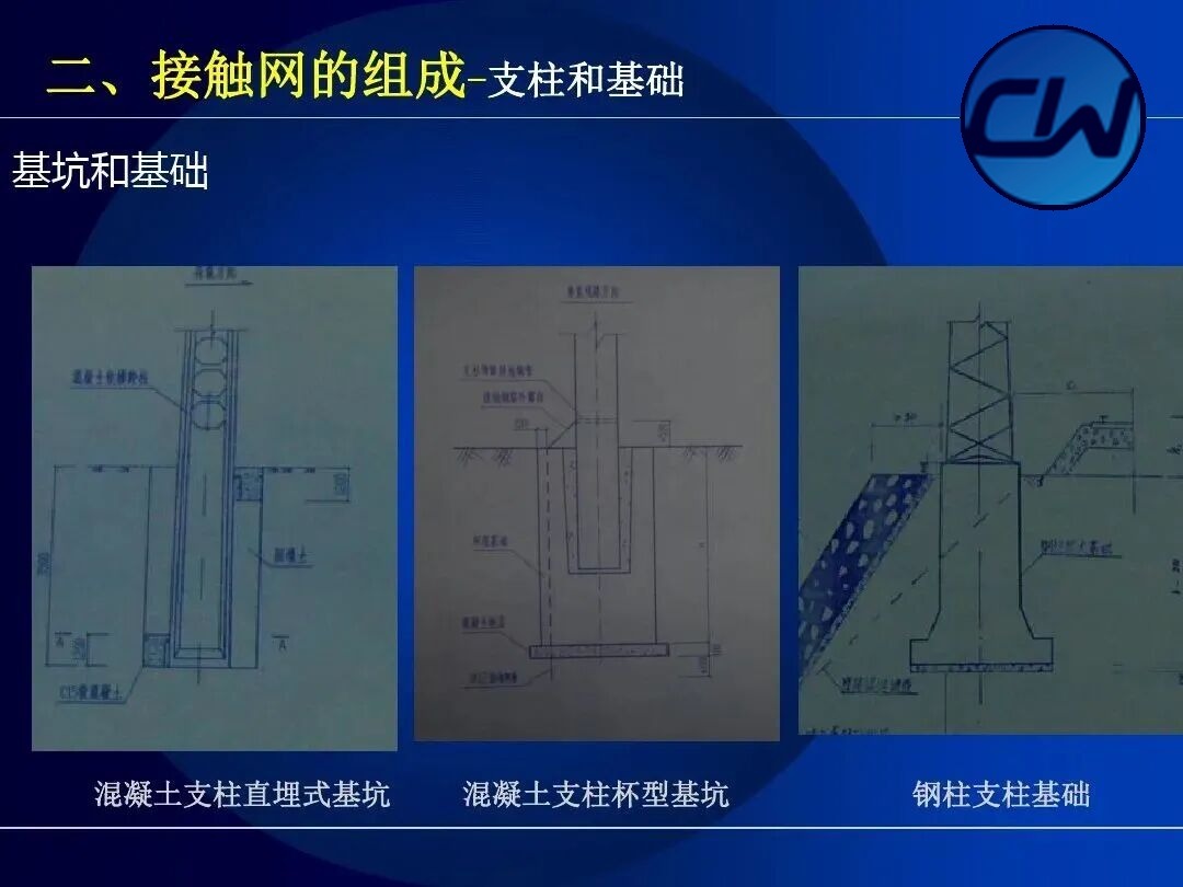
By material masts are divided into concrete masts and steel masts. Concrete masts are low in cost, corrosion-resistant and long-lived; steel masts are strong and easy to transport. By the role they play in the OCS, masts are classified as intermediate masts, transition masts, centre masts, anchor masts, turnout masts, flexible cross-span masts, rigid cross-span masts and bridge masts.
III. Suspension Types of the OCS
Related products: Contact suspension · Compensation device · Positioning device
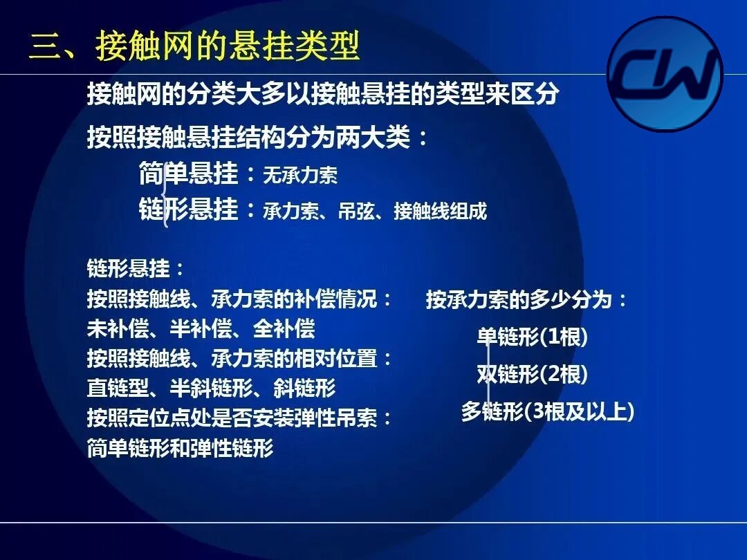
The OCS is classified mainly by the type of contact suspension. By structure of the contact suspension there are two broad classes: simple suspension, without a messenger wire, and catenary suspension, made up of messenger wire, droppers and contact wire. Catenary suspension is further subdivided in several ways:
- By the compensation of the contact wire and messenger wire: uncompensated, semi-compensated and fully compensated.
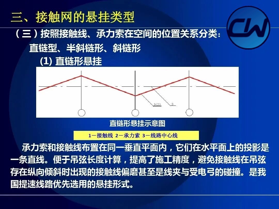
- By the relative position of the contact wire and messenger wire: straight catenary, semi-oblique catenary and oblique catenary.
- By the number of messenger wires: single catenary (1 wire), double catenary (2 wires) and multiple catenary (3 wires or more).
- By whether elastic droppers are fitted at the positioning points: simple catenary and elastic catenary.
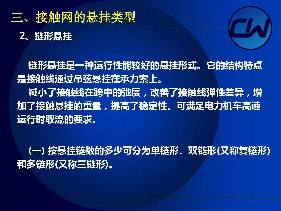
3.1 Simple catenary suspension
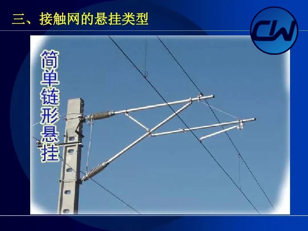
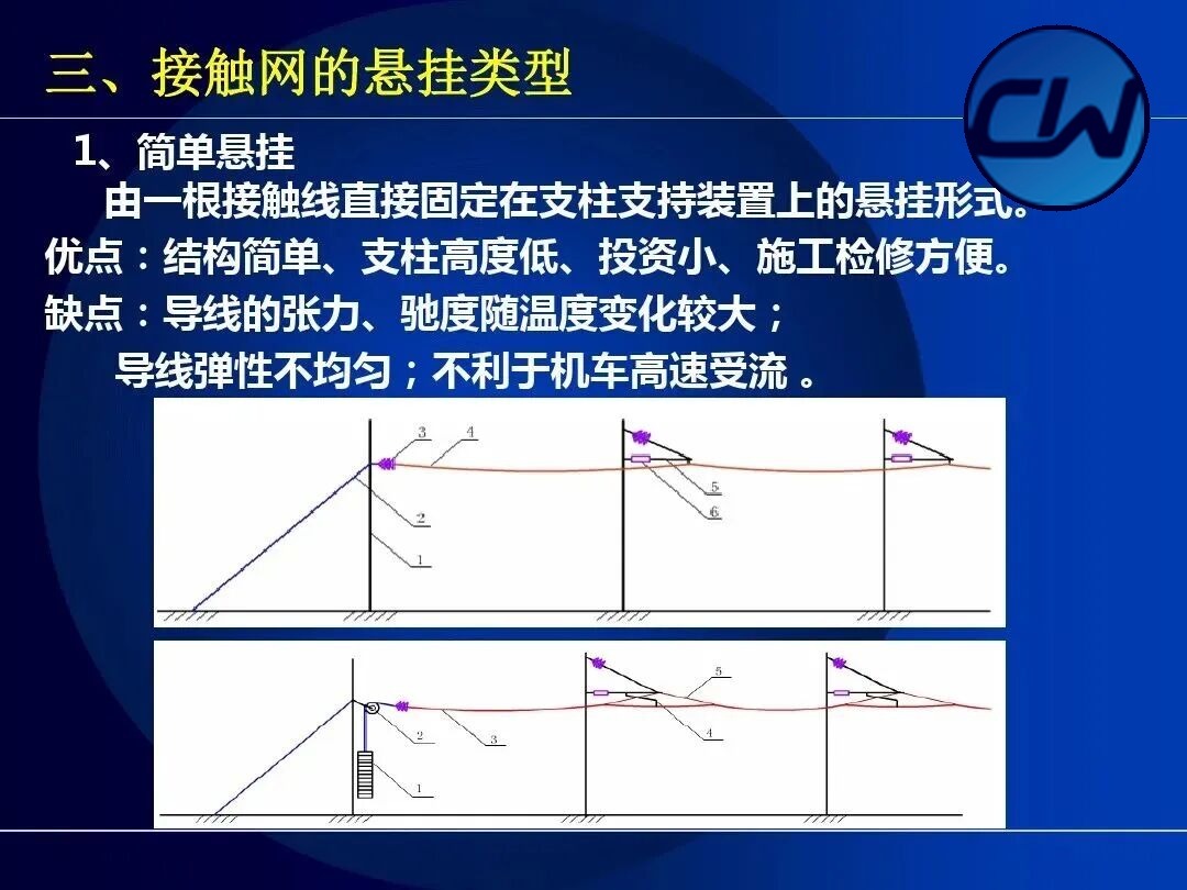
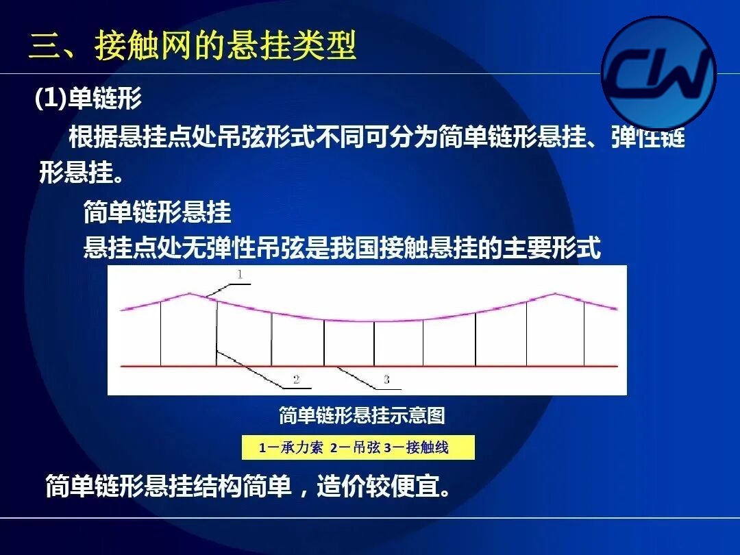
Simple catenary suspension is a simplified form of catenary suspension made up mainly of messenger wire, droppers and contact wire, without elastic droppers. It is simple in structure and low in cost and is used mainly in station yards and on lower-speed sections.
3.2 Elastic catenary suspension
Elastic catenary suspension adds elastic droppers (Y-type or Π-type) at the positioning points to the simple catenary arrangement. This improves the elasticity of the contact wire at the positioning point, makes the contact force between pantograph and contact wire more uniform and favours current collection when the locomotive runs at high speed.
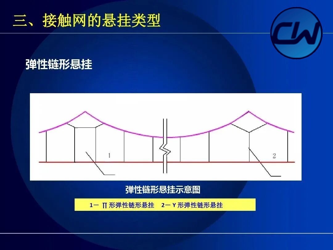
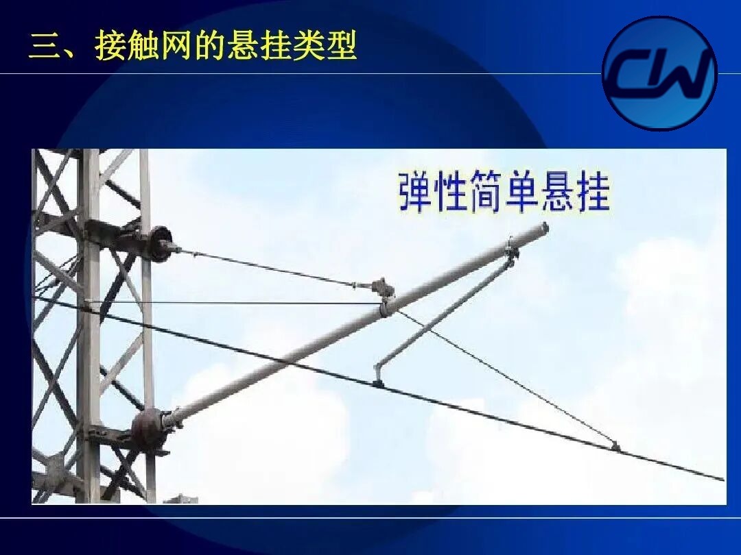
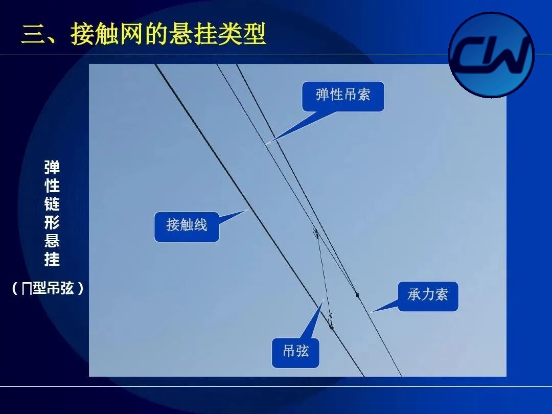
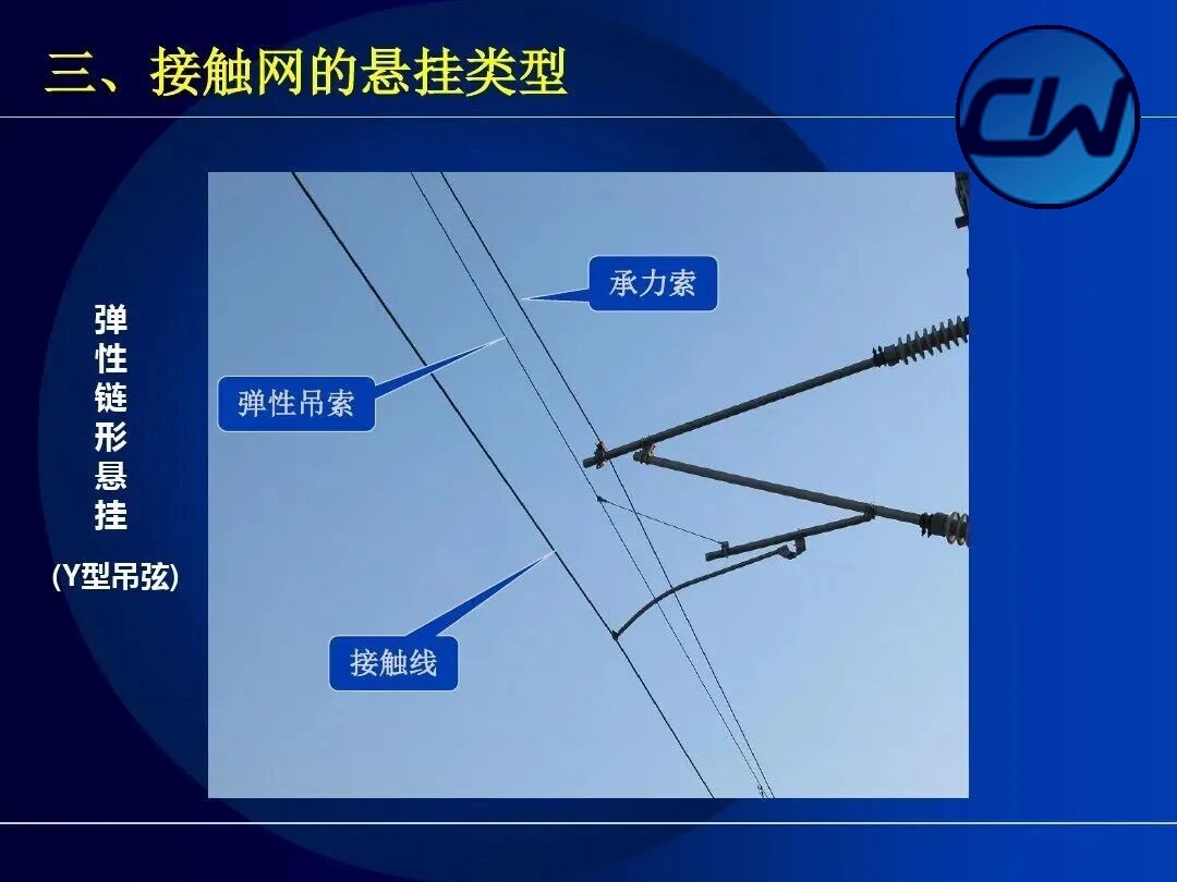
3.3 Semi-oblique catenary suspension
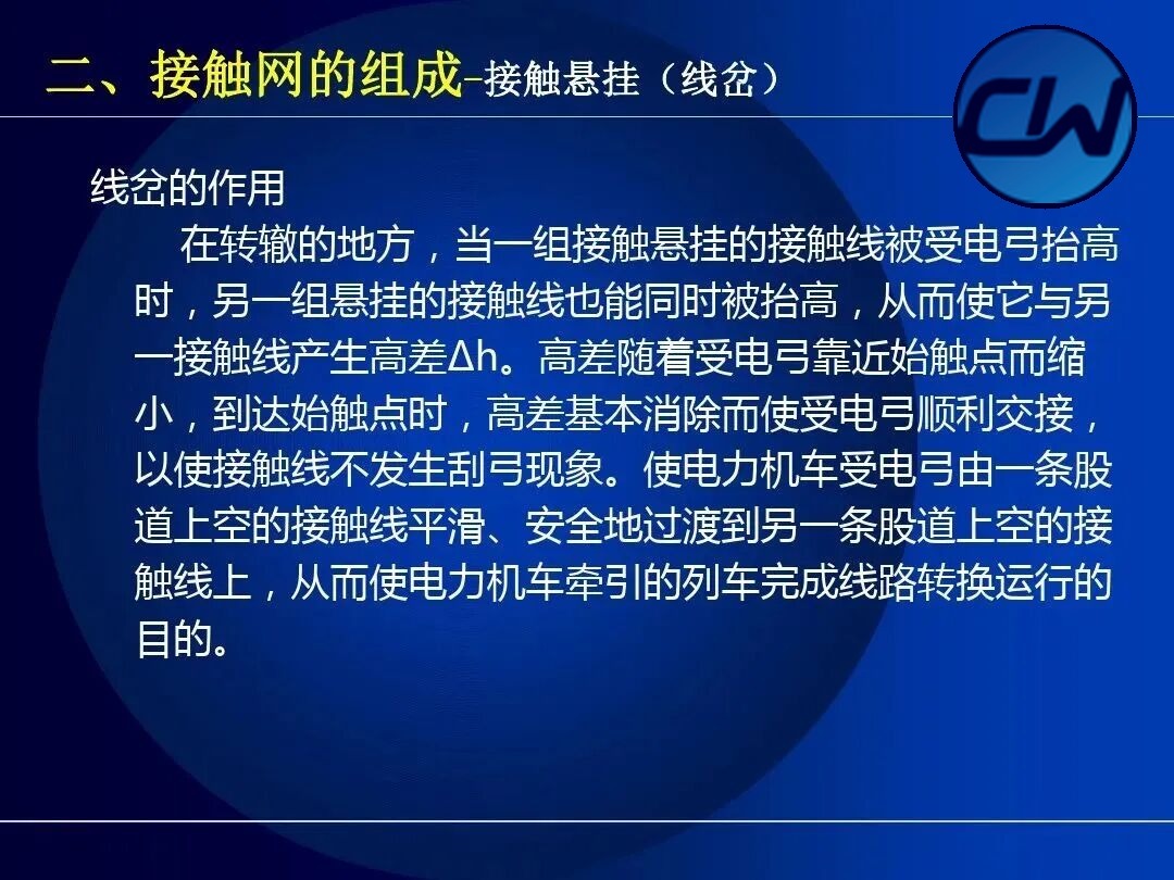
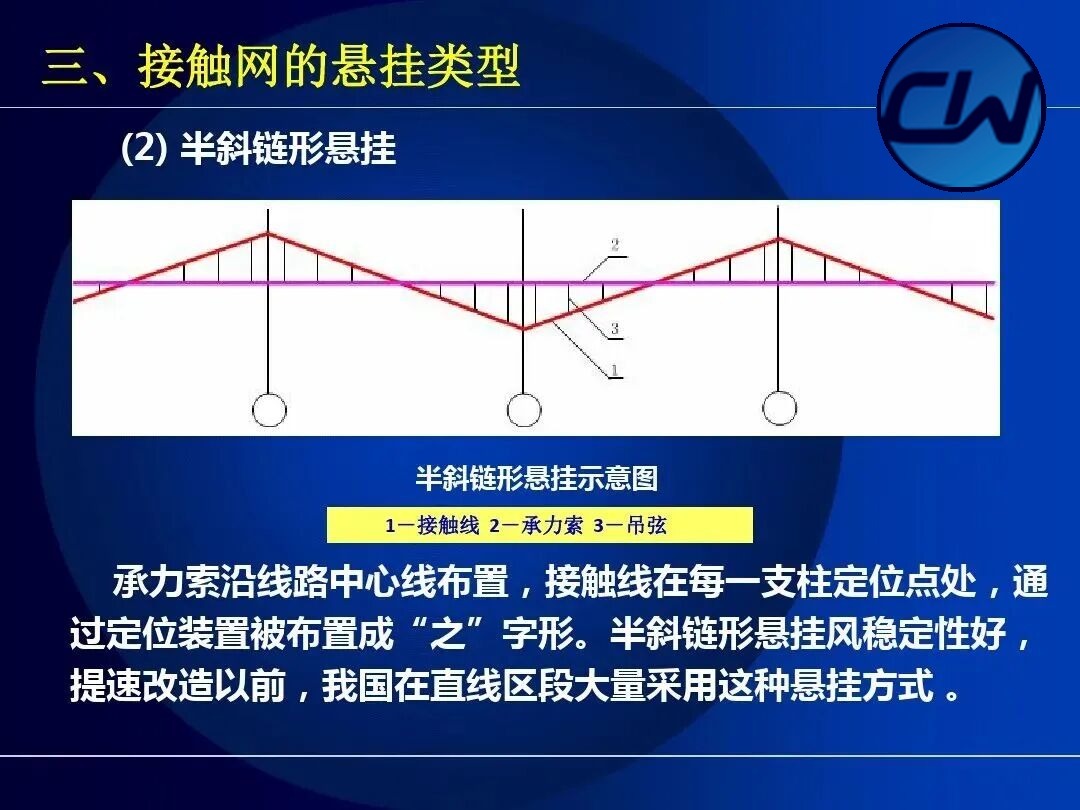
In semi-oblique catenary suspension the messenger wire follows the centre line of the track while the contact wire is staggered into a zigzag at each mast positioning point by the positioning device. Semi-oblique suspension has good stability against wind, and before the speed-raising upgrading it was widely used on straight track in China.
3.4 Oblique catenary suspension
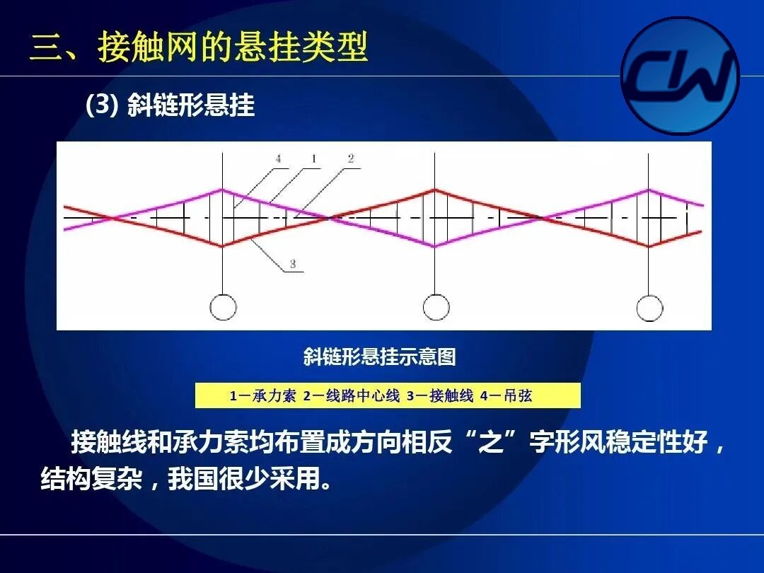
In oblique catenary suspension both the contact wire and the messenger wire are staggered into zigzags of opposite direction. It is stable against wind but complex in structure and is now seldom used in China.
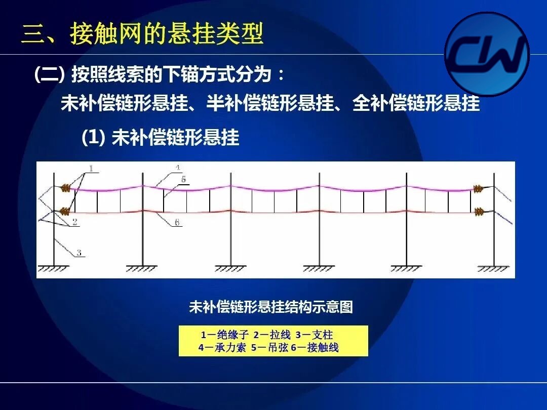
3.5 Catenary suspension with various compensation arrangements
By compensation, catenary suspension is classified as follows:
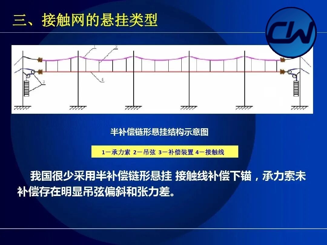
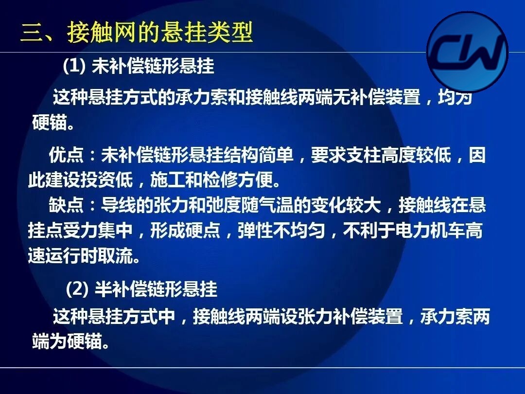
- Uncompensated catenary suspension: no compensation device at either end of the messenger wire or the contact wire, both being hard-anchored. The structure is simple, the masts can be lower, the construction cost is low and erection and maintenance are convenient, but the tension and sag of the conductors vary considerably with temperature, which is unfavourable for current collection at high speed.
- Semi-compensated catenary suspension: tension compensation devices are fitted at both ends of the contact wire while the messenger wire is hard-anchored at both ends.
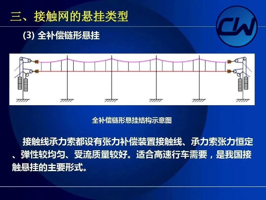
- Fully compensated catenary suspension: compensation devices are fitted at both ends of both the contact wire and the messenger wire, so that conductor tension is adjusted automatically. Operating performance is good, but the structure is complex and the cost high.
IV. Feeding Methods of the OCS
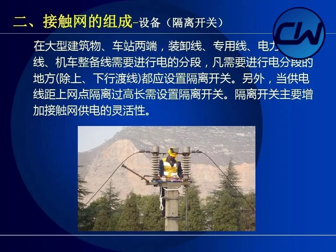
Related products: Phase-break insulator · Sectioning insulator · Disconnector · Contact suspension
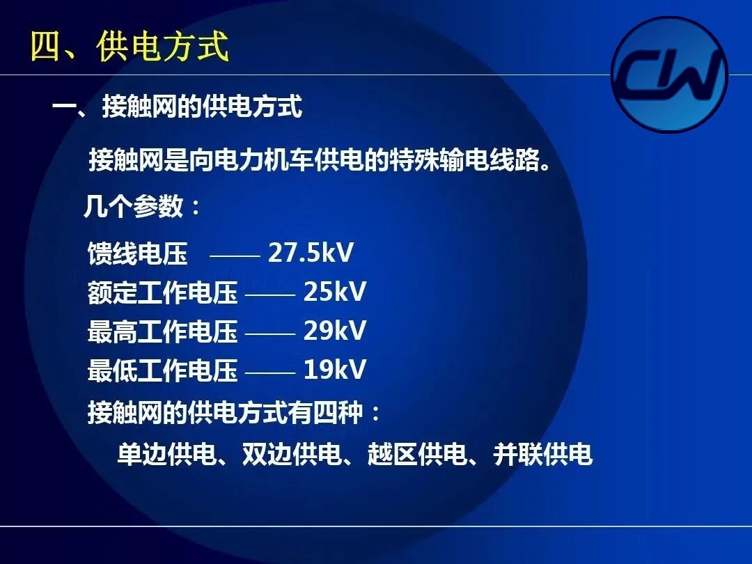
The OCS is a special transmission line supplying electric locomotives. The main parameters are: feeder voltage 27.5 kV, rated operating voltage 25 kV, maximum operating voltage 29 kV and minimum operating voltage 19 kV. There are four feeding arrangements: single-end feeding, double-end feeding, cross-zone feeding and parallel feeding.
4.1 Direct feeding (TR)
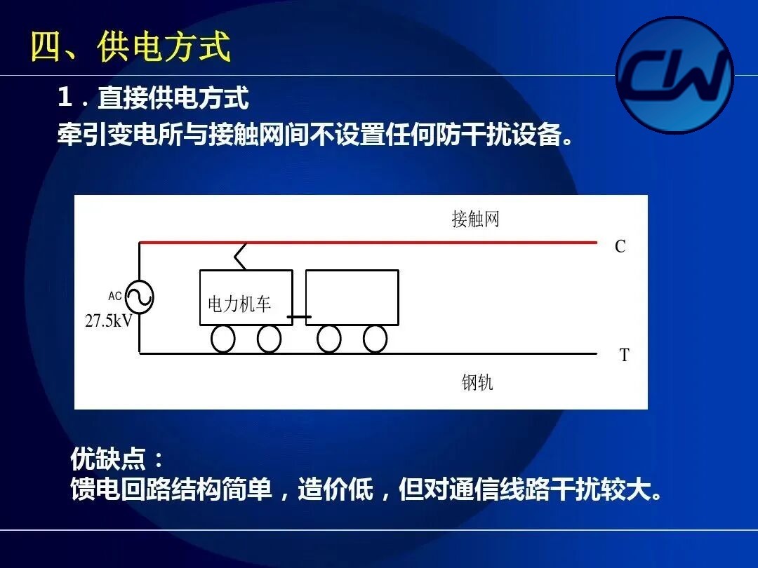
In direct feeding there is no interference-suppression equipment of any kind between the traction substation and the OCS. The feeding circuit is simple in structure and low in cost, but it interferes fairly strongly with communication lines.
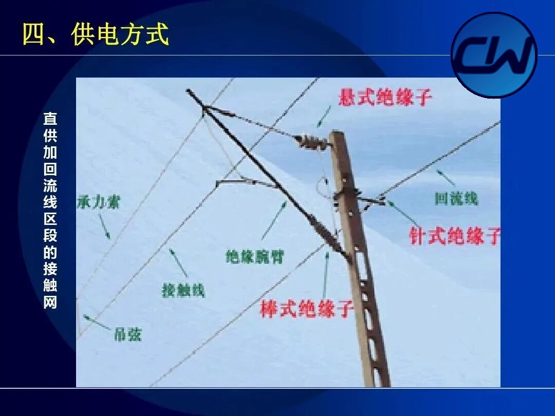
4.2 Direct feeding with return conductor (TRNF)
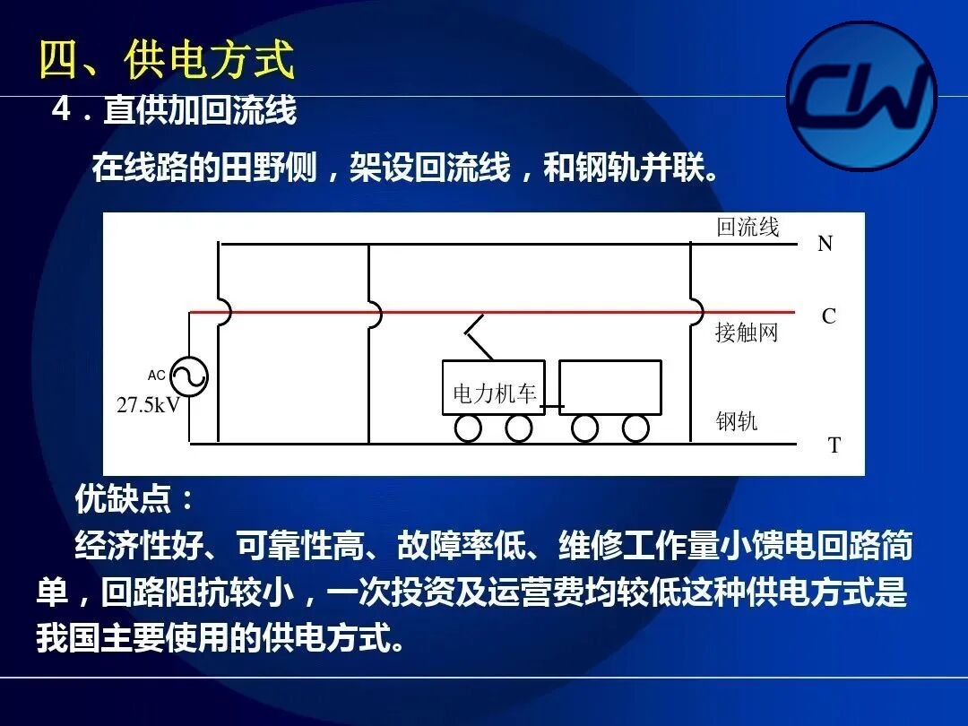
Direct feeding with return conductor adds a return conductor (N wire) running parallel to the OCS, which reduces interference with communication lines.
4.3 AT feeding (autotransformer feeding)
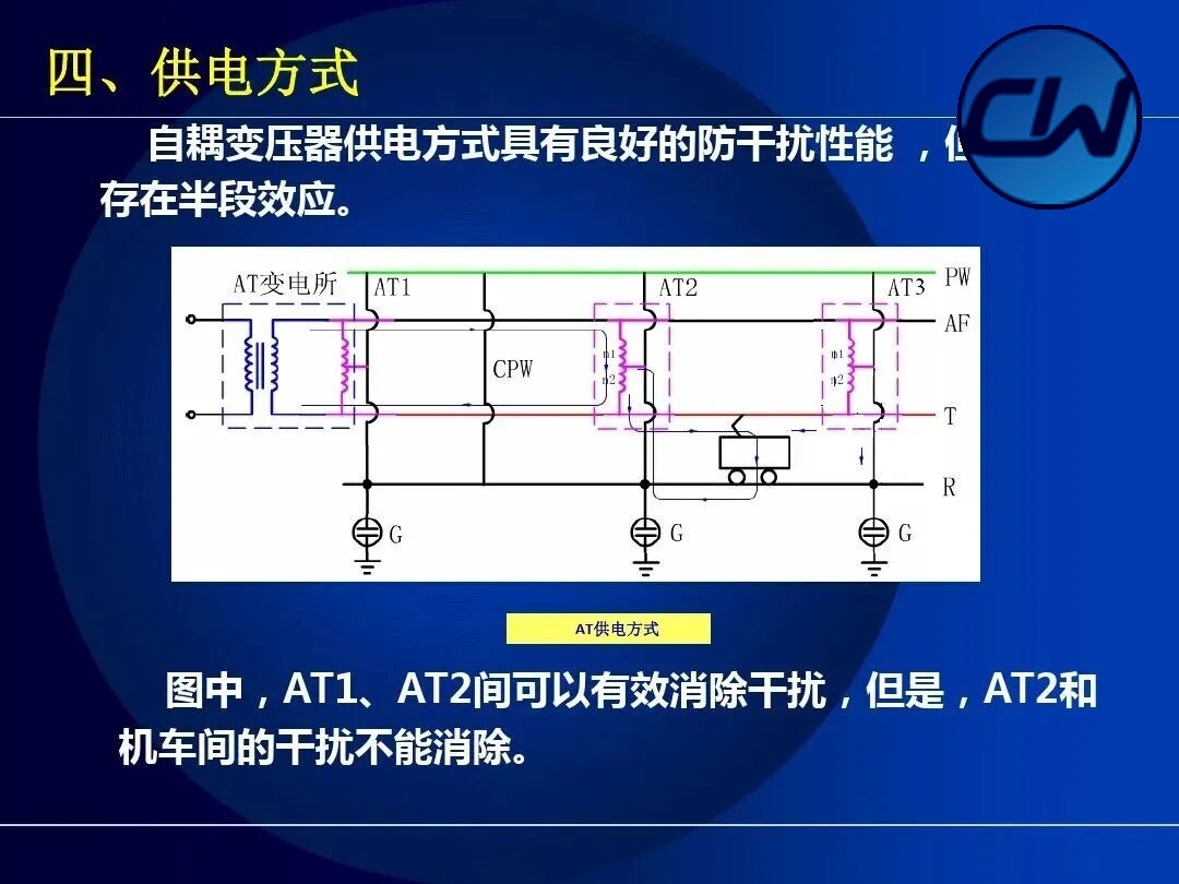
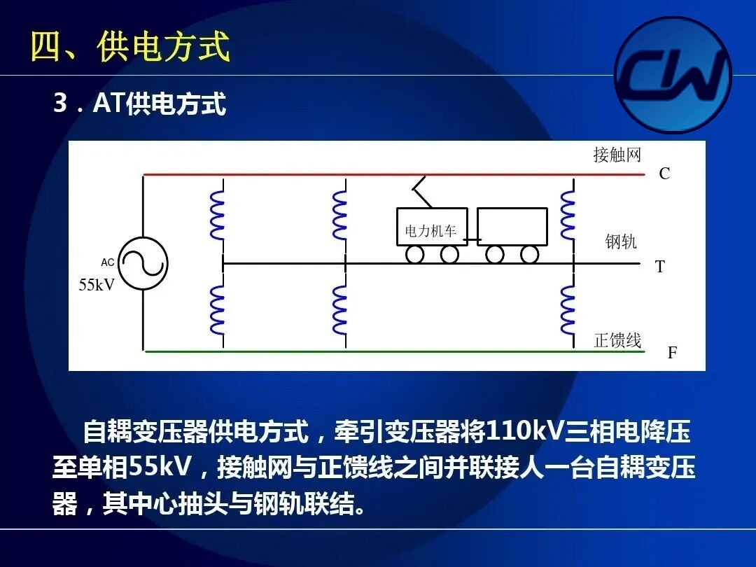
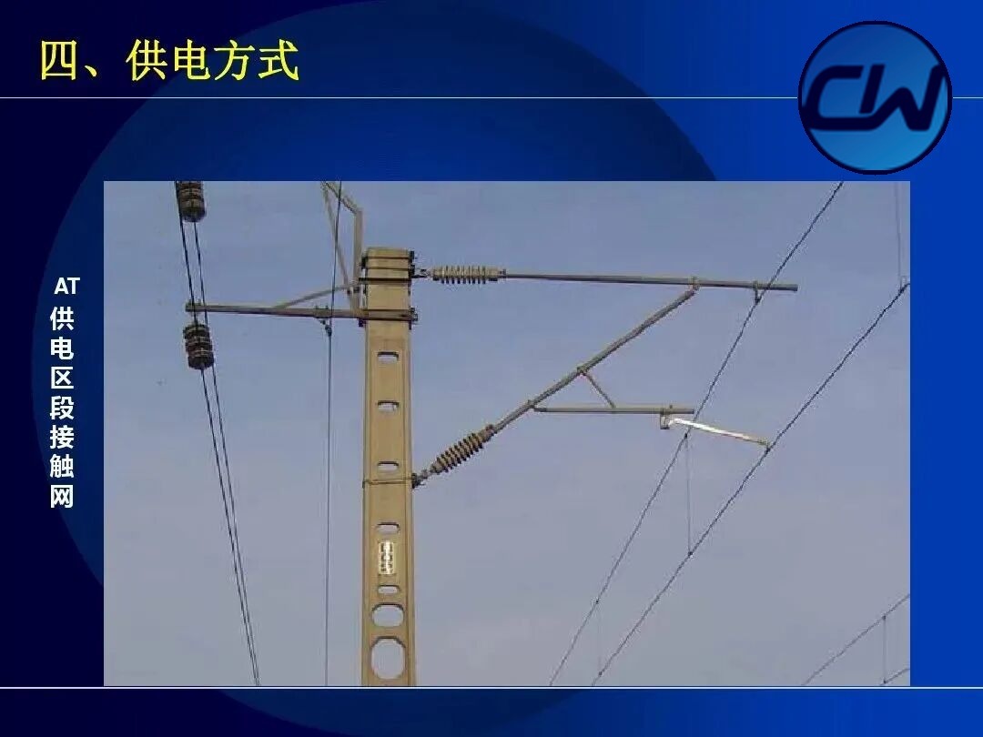
In autotransformer feeding the traction transformer steps the 110 kV three-phase supply down to single-phase 55 kV, and an autotransformer is connected in parallel between the OCS and the positive feeder, with its centre tap connected to the rails. This arrangement gives long feeding arms, high supply quality and little interference with communications, and it is the dominant feeding method of high-speed electrified railways.
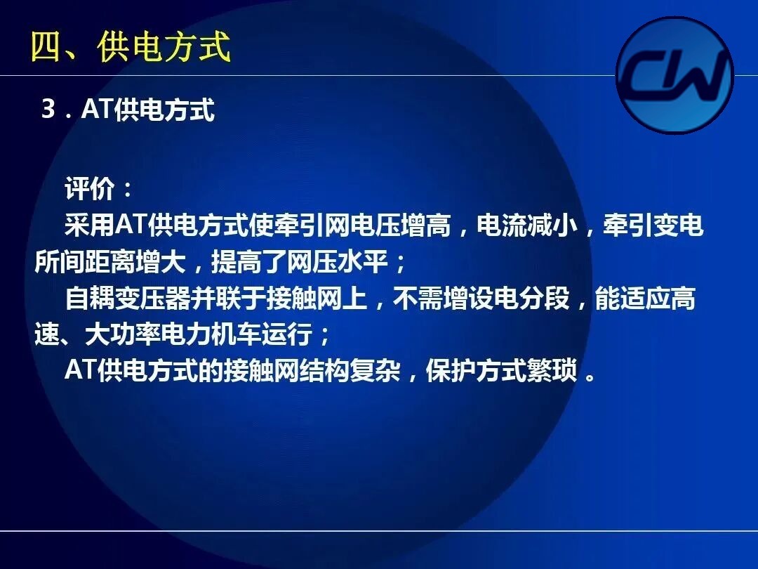
4.4 BT feeding (booster transformer feeding)
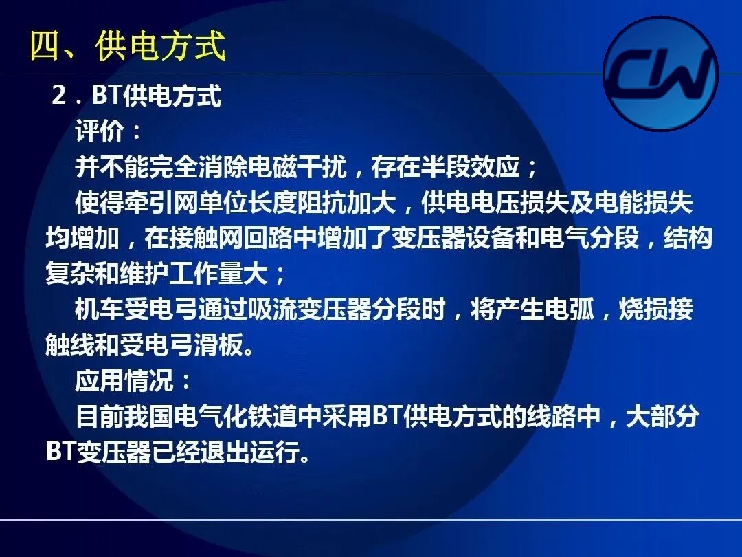
When the traction current flows through the primary of the booster transformer, most of the current that would flow through the rails is forced through the booster wire into the return conductor and back to the traction substation. Because the current in the return conductor cancels the greater part of the electromagnetic induction produced by the OCS current, the influence on communication lines is greatly reduced.
4.5 Categories of feeding arrangement: single-end, double-end, cross-zone and parallel
There are four feeding arrangements for the OCS:
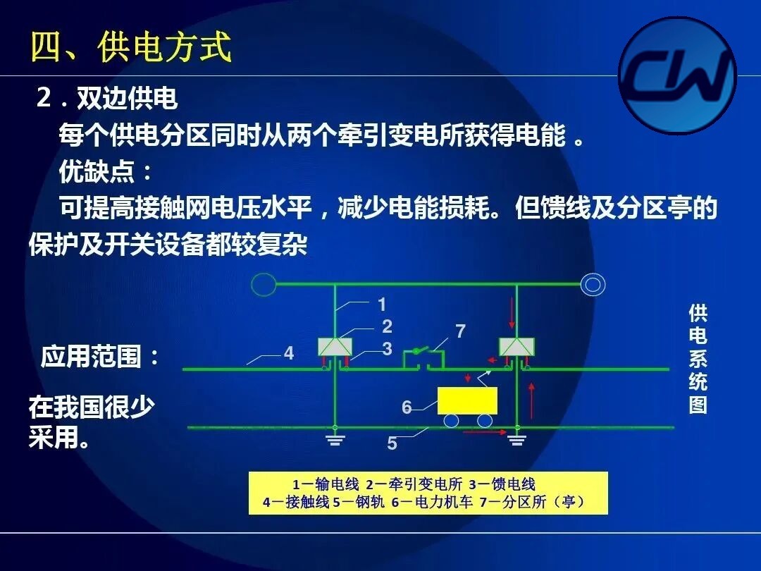
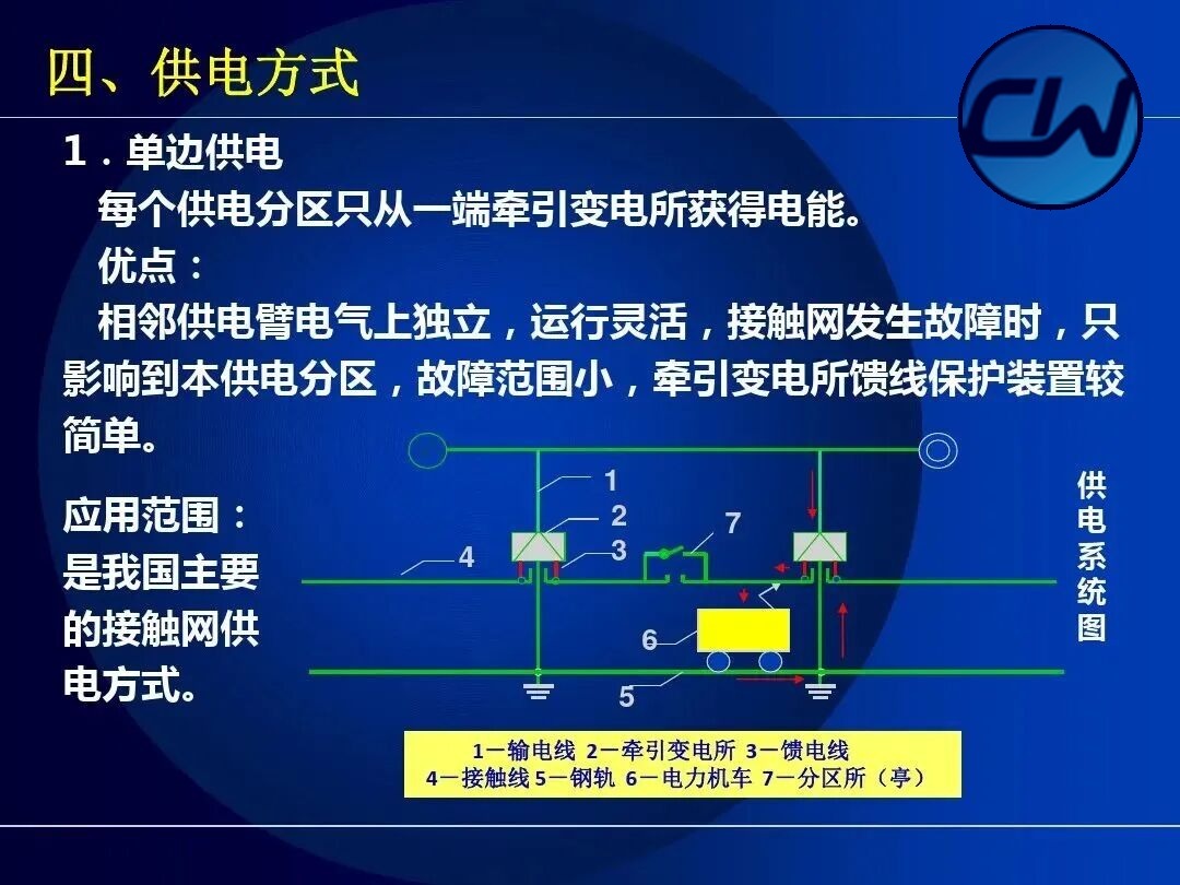
- Single-end feeding: each feeding section receives energy from the traction substation at one end only. Adjacent feeding arms are electrically independent, operation is flexible, the extent of a fault is small and the feeder protection is relatively simple; this is the main feeding arrangement used in China.
- Double-end feeding: traction substations are connected at both ends of the feeding section, giving high supply reliability.
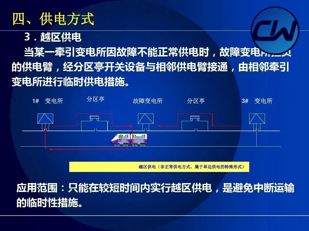
- Cross-zone feeding: when a traction substation fails, an adjacent substation feeds across the zone.
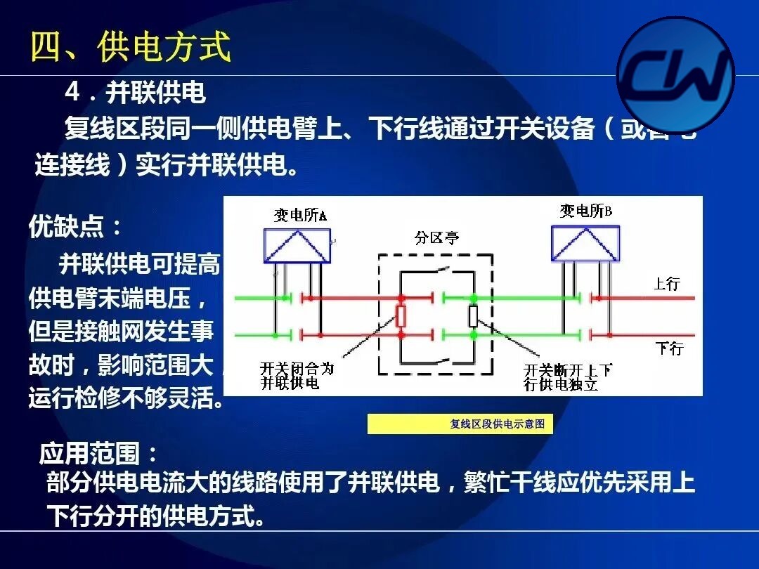
- Parallel feeding: in hub stations or yards several feeding arms are operated in parallel.
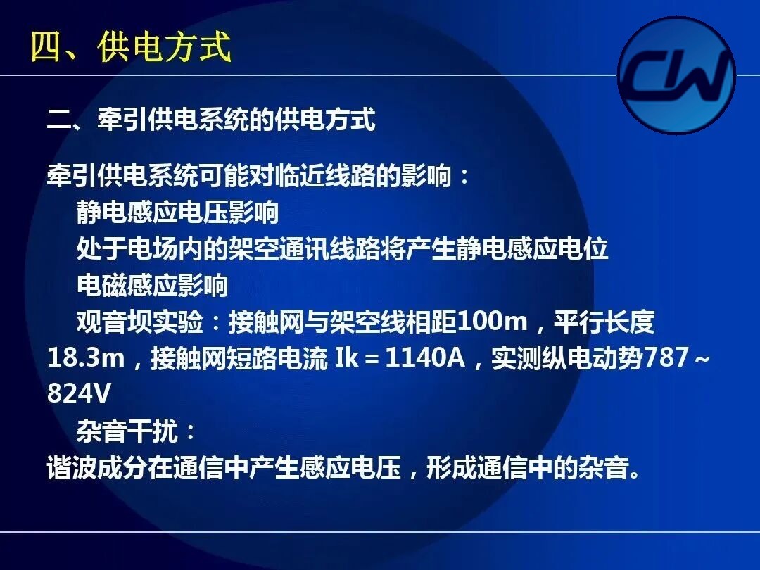
4.6 Influence of the traction supply system on adjacent lines
The traction supply system may influence adjacent lines in the following ways:
- Electrostatic induced voltage: an overhead communication line inside the electric field acquires an electrostatic induced potential.
- Electromagnetic induction: in the Guanyinba test the OCS and the overhead line were 100 m apart with a parallel length of 18.3 m; with an OCS short-circuit current Ik = 1140 A the measured longitudinal electromotive force was 787~824 V.
- Noise interference: harmonic components induce a voltage in the communication circuit and produce noise in communication.
4.7 OCS feeder protection
OCS feeder protection comprises impedance protection, instantaneous overcurrent protection and definite-time overcurrent protection.
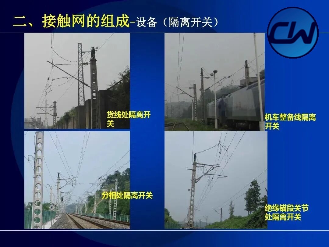
2.5 Additional examples of equipment (phase-break and sectioning insulators)
The following are further field examples of phase-break and sectioning insulators:
2.6 Supplementary contact suspension
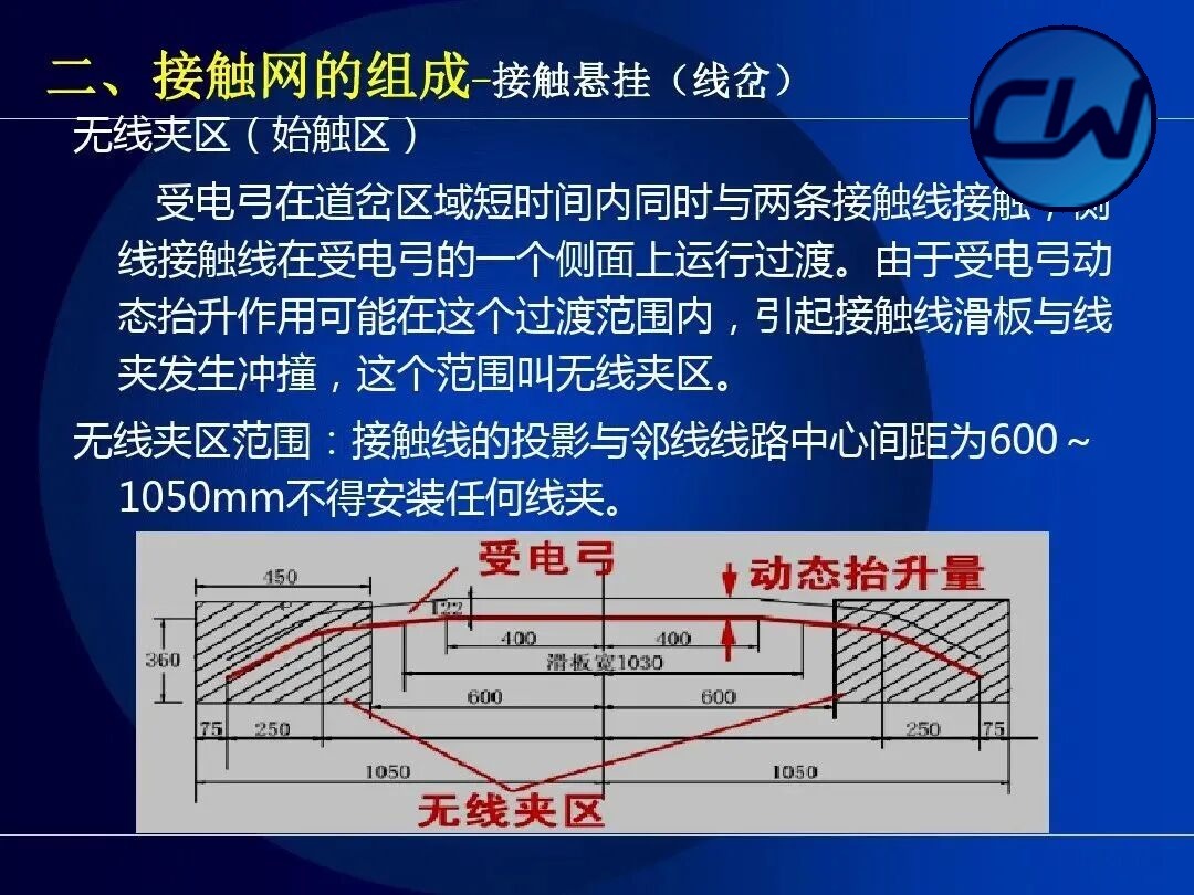
The following are further schematic views of the contact suspension:
Conclusion
Through systematic study of this course we have come to understand the four core modules of the OCS: basic structure, constituent equipment, suspension types and feeding methods. As the core supply facility of an electrified railway, the OCS must be designed, erected and maintained in strict accordance with technical standards so that electric locomotives run safely and reliably.
The course is intended for:
- Induction training for OCS workers
- Professional study by signalling and electrical trainees
- Reference material for engineering and technical staff
- Teaching support material for railway colleges
112 teaching slides in total · a systematic explanation of OCS fundamentals
Usage Notes
Further reading: Contact suspension system · Complete technical analysis of sectioning insulators · Illustrated inspection guide for OCS components · Metro OCS component identification atlas · AT feeding with fully compensated catenary suspension · Heavy-haul high-tension reinforced solution · Condition assessment by multi-source data fusion
- This course contains 112 teaching slides, arranged in four modules: basic structure, constituent equipment, suspension types and feeding methods.
- Each slide is captioned with its original page number and its chapter. Clicking an image opens the full-size original in a new tab, which makes field comparison and detailed inspection easier.
- The key parameters shown in the figures (tension, gradient, voltage level and so on) follow the latest industry technical standards; where they differ from the regulations in force, the regulations in force prevail.
- It is recommended to study alongside the current maintenance process documents and equipment models of your own organisation. The material can serve as induction training for OCS workers and as study material for new employees taking up their posts.