OCS Component Inspection Guide Album (All 16 Categories)
Abstract
This album systematically compiles field inspection guide diagrams for the main components of the overhead contact system, covering 16 major categories: support devices, positioning devices, electrical connections, five-span anchor joints, midpoint anchors, pulley and ratchet tensioning devices, non-crossing and crossing wire crossings, phase separation joints, surge arresters, disconnectors, suction lines, auxiliary suspension anchors, tunnel embedments and hanger posts, and in-tunnel tensioning anchors. Each diagram is a standardised inspection diagram actually used on engineering sites, giving the position of every component, the torque specification, the installation requirements and examples of typical errors. It is a portable reference for OCS patrol inspection, maintenance, training and acceptance.
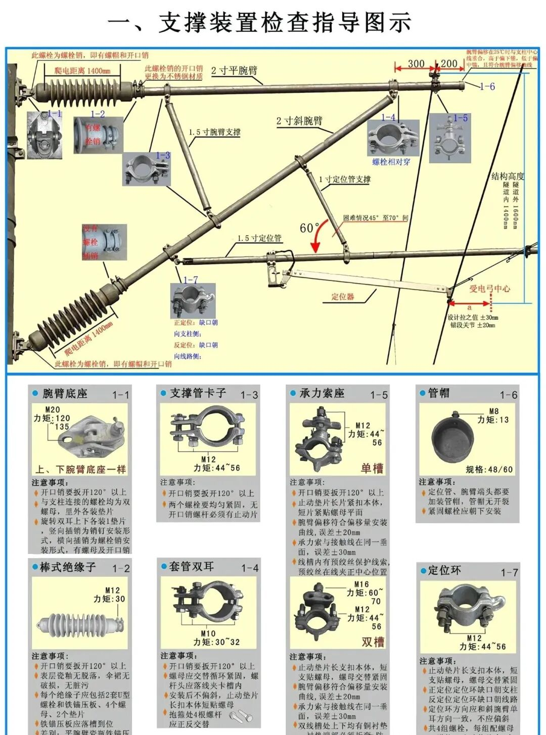
Fig. 1-1 Inspection guide diagram for support devices (click to view a larger image)
Key points:The installation arrangement, tightening torque, component material, pin and split-pin specifications and the inspection focus of each part of the cantilever base, rod insulator, support tube clip, sleeve double lug, messenger wire support, positioning ring and pipe cap.
2. Inspection Guide Diagram for Positioning Devices (POSITIONING DEVICE)
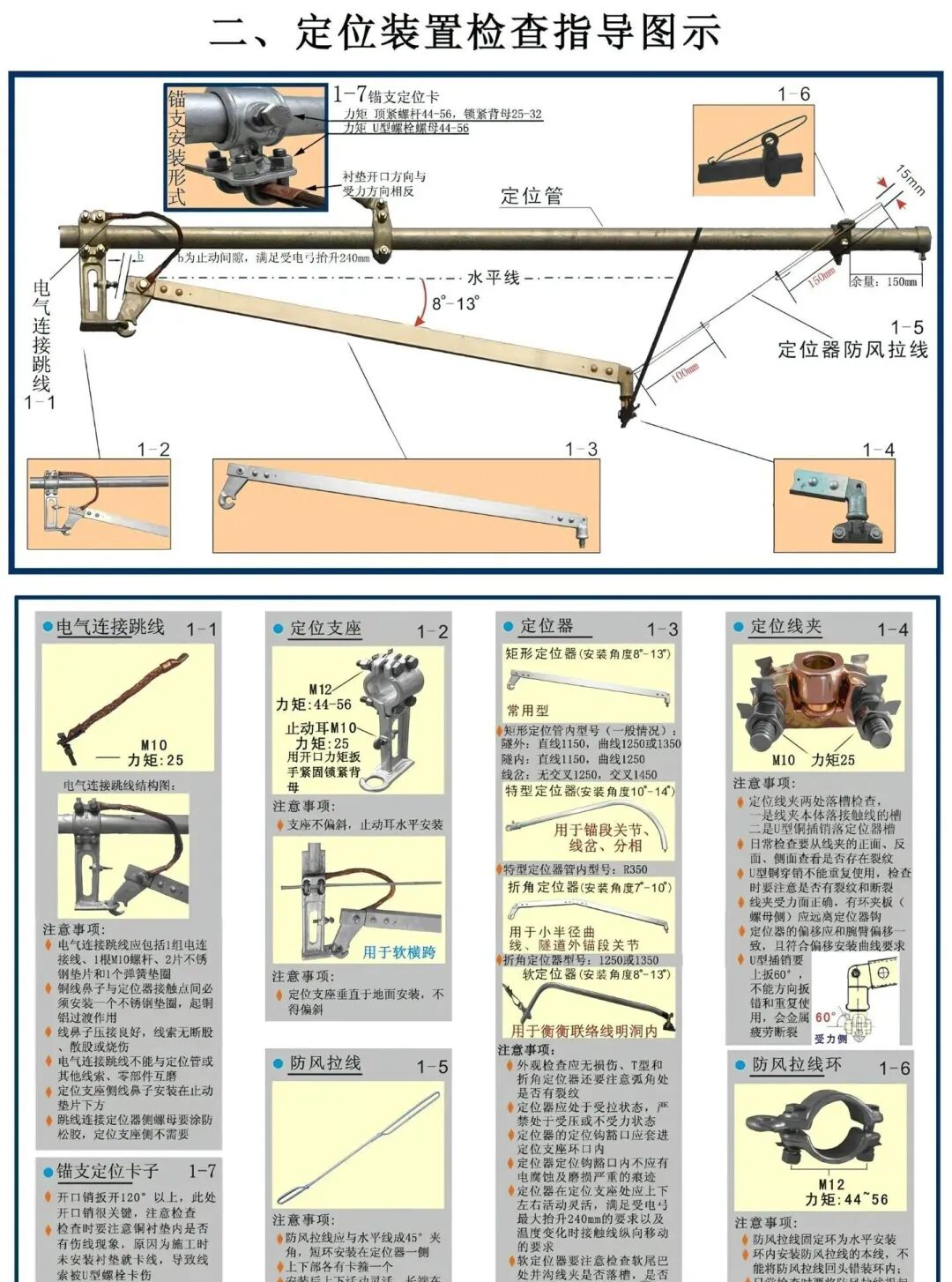
Steady armPositioning clampWind-resistant guy wireAnchor branch positioning clipa value 100±20mm
Fig. 2-1 Inspection guide diagram for positioning devices (click to view a larger image)
Key points:The installation angle (8°~13°) of the electrical bonding jumper, steady arm bracket, steady arm (rectangular / special-profile / bent / hook type), positioning clamp, wind-resistant guy wire and anchor branch positioning clip; the a value (stagger), the orientation of the loaded face, the bolt tightening torque and the condition of the pins.
3. Inspection Guide Diagram for Electrical Connections (ELECTRICAL CONNECTION)
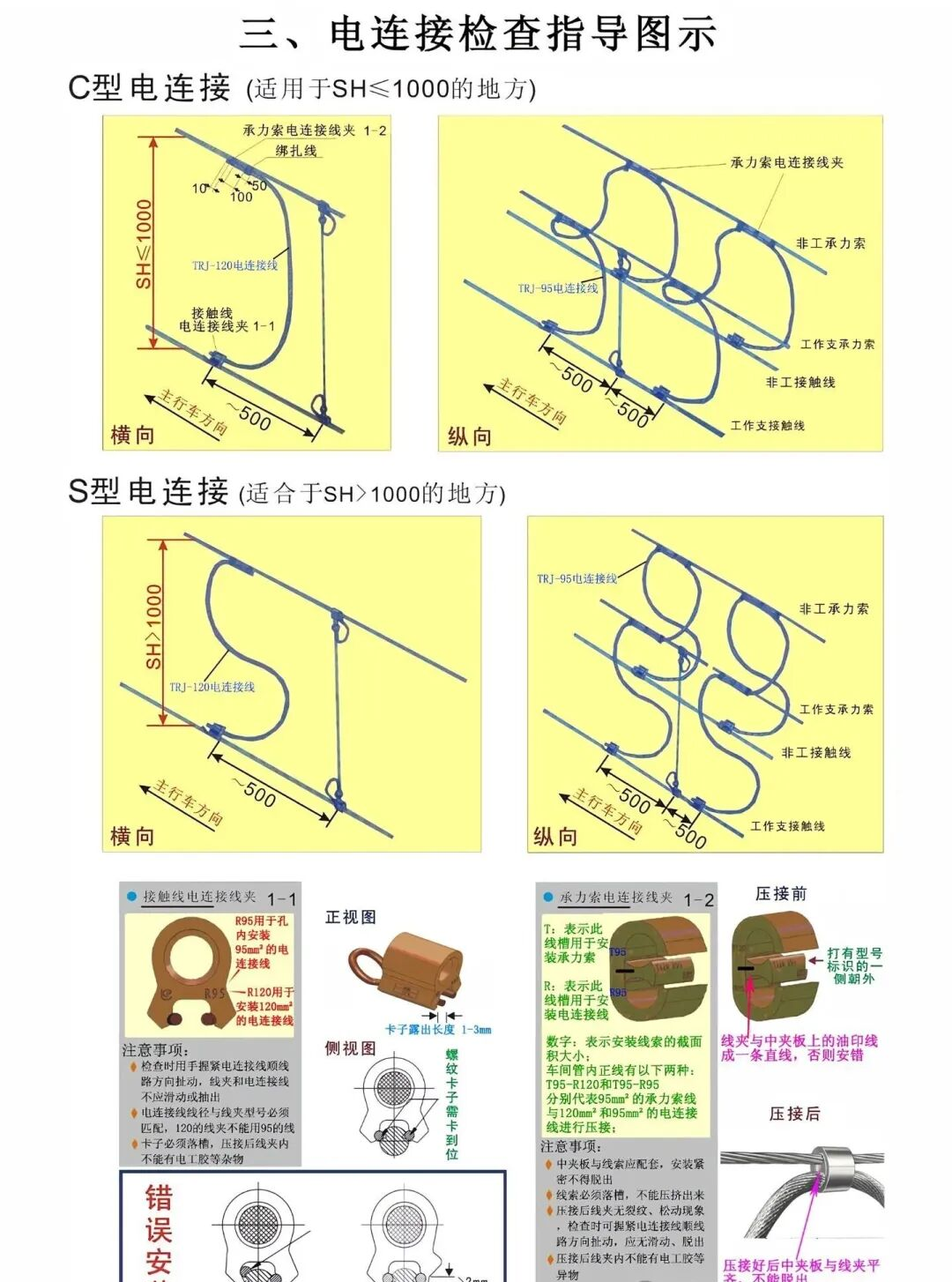
Fig. 3-1 Inspection guide diagram for electrical connections (click to view a larger image)
Key points:The transverse and longitudinal arrangement of C-type electrical connections (SH≤1000) and S-type electrical connections (SH>1000); model matching of contact wire and messenger wire electrical connection clamps (R95/R120/T95/T70), the crimping procedure and examples of incorrect installation.
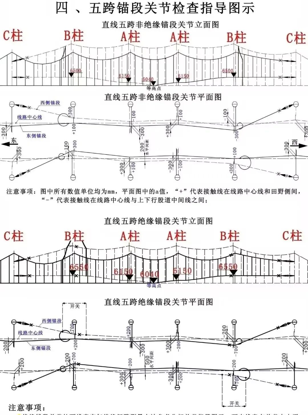
Non-insulated jointInsulated jointEqual-height pointAir gap 500mm±20mm
Fig. 4-1 Inspection guide diagram for five-span anchor joints (click to view a larger image)
Key points:The elevation and plan views of a straight five-span non-insulated / insulated anchor joint, showing the position of posts C-B-A-A-B-C, the a value (stagger), the contact wire heights (6500/6150/6040 mm) and the location of the equal-height point; the air gap between the two wires of an insulated joint is 500mm±20mm.
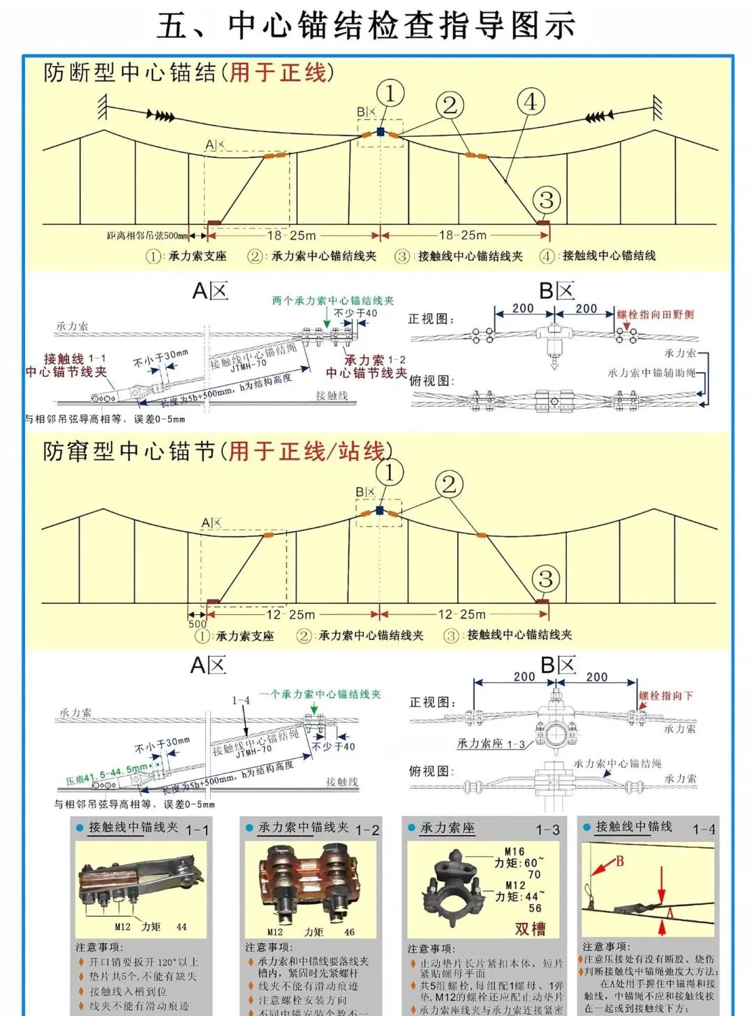
5. Inspection Guide Diagram for Midpoint Anchors (MIDPOINT ANCHOR)
Anti-breakage typeAnti-creep typeMessenger wire midpoint anchorContact wire midpoint anchor500mm from the adjacent suspension
Fig. 5-1 Inspection guide diagram for midpoint anchors (click to view a larger image)
Key points:The layout of the anti-breakage midpoint anchor (used on main lines) and the anti-creep midpoint anchor (used on main lines and station tracks), the detail drawings of zone A and zone B, the models, torque and crimping procedure of the messenger wire and contact wire midpoint anchor clamps, and the requirement that the contact wire height equals that at the adjacent suspension (tolerance 0~5mm).
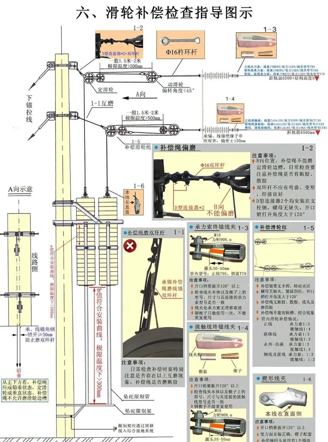
6. Inspection Guide Diagram for Pulley Tensioning Devices (PULLEY COMPENSATION)
Compensation ropeCompensation pulley setMessenger wire terminal anchorageExtreme temperature 1.5~2m
Fig. 6-1 Inspection guide diagram for pulley tensioning devices (click to view a larger image)
Key points:The installation of the compensation rope winding, the Φ16 anchor rod, the D-type connector, the double-eye rod of the compensation rope, the messenger wire terminal anchorage and the wedge clamp; the deflection angle of the fixed pulley ≤45°; the balance weights within the 300mm guide frame; compensation ratio: messenger wire 1:3 / contact wire 1:4.
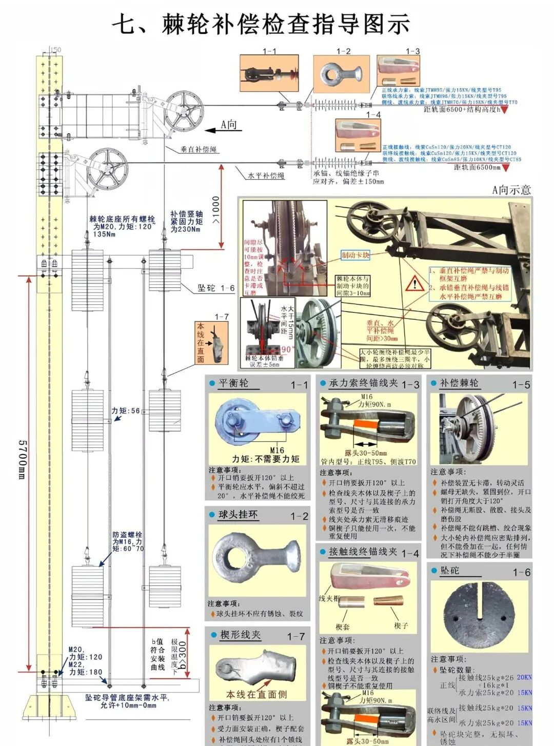
7. Inspection Guide Diagram for Ratchet Tensioning Devices (RATCHET COMPENSATION)
Ratchet bodyBalance wheelBrake blockCompensation rope ≥ half a turn
Fig. 7-1 Inspection guide diagram for ratchet tensioning devices (click to view a larger image)
Key points:The torque of the ratchet base bolts 120~135 N·m; the clearance between the ratchet body and the brake block 3~10mm; on large-wheel ratchet tensioning devices the compensation rope shall be arranged closely and evenly; vertical and horizontal compensation ropes must never rub against each other; number of balance weights: contact wire 25kg×20 pieces 20KN + 16kg×1, messenger wire 25kg×20 pieces 15KN.
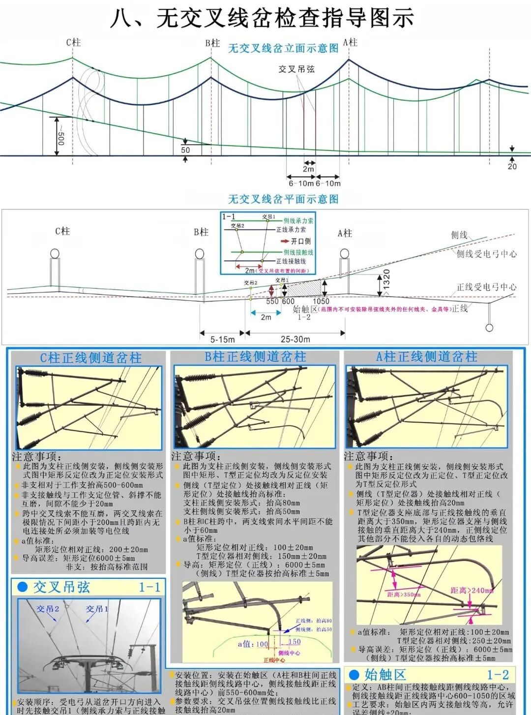
8. Inspection Guide Diagram for Non-Crossing Wire Crossings (NON-CROSSING FROG)
Initial contact zoneCrossing droppera value standardLift 80mm / 50mm
Fig. 8-1 Inspection guide diagram for non-crossing wire crossings (click to view a larger image)
Key points:The installation arrangement of the turnout posts on the main line side of posts C / B / A (rectangular or T-type steady arm), the extent of the initial contact zone, the a value standard (rectangular 200±20mm / T-type 100±20mm), the contact wire height tolerance (6000±5mm), and the inclination angle of the crossing dropper clamp on the contact wire <15°.
9. Inspection Guide Diagram for Crossing Wire Crossings (CROSSING FROG)
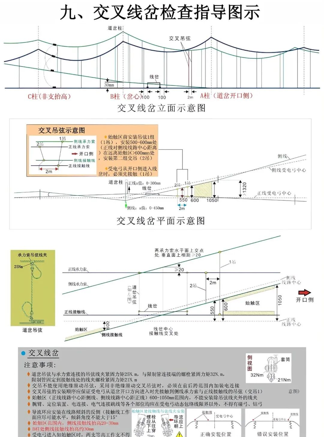
Fig. 9-1 Inspection guide diagram for crossing wire crossings (click to view a larger image)
Key points:The turnout post, the centre of the wire crossing, the initial contact zone (main line 600~1050mm, side track 550~600mm) and the a value 0~450mm; the tightening torque of the dropper clamp connecting the turnout dropper to the messenger wire 25 N·m; the tightening torque at the connecting end of the limit tube 32 N·m; the contact wire is raised by 20~30mm within the initial contact zone.
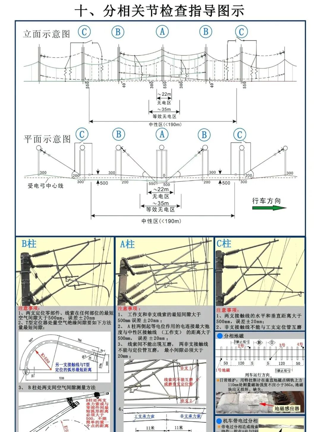
Dead zoneNeutral zonePosts A / B / CNeutral zone <190m
Fig. 10-1 Inspection guide diagram for phase separation joints (click to view a larger image)
Key points:The five-span C-B-A-A-B-C phase separation layout, the dead zone of 22m, the equivalent dead zone of 35m and the neutral zone <190m; the electrical connections on both sides of post A and the distance from the insulator shed edge to the contact wire of the working branch >400mm; the air insulation gap measured at the T-type steady arm; the phase separation ground magnetic sensor (110mm above the rail surface).
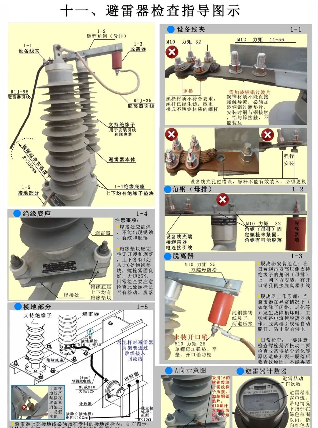
11. Inspection Guide Diagram for Surge Arresters (LIGHTNING ARRESTER)
Support insulatorArrester disconnectorCounterDisconnector lead RTJ-35
Fig. 11-1 Inspection guide diagram for surge arresters (click to view a larger image)
Key points:The installation of the arrester body, insulating base, earthing part, arrester disconnector and counter; the tightening torque of the galvanised angle steel (busbar) and equipment clamps, together with examples of incorrect installation (copper-aluminium transition, wrong material); the resistance of the earthing lead up to the counter <10Ω; the reading position of the counter (green = normal, red = abnormal).
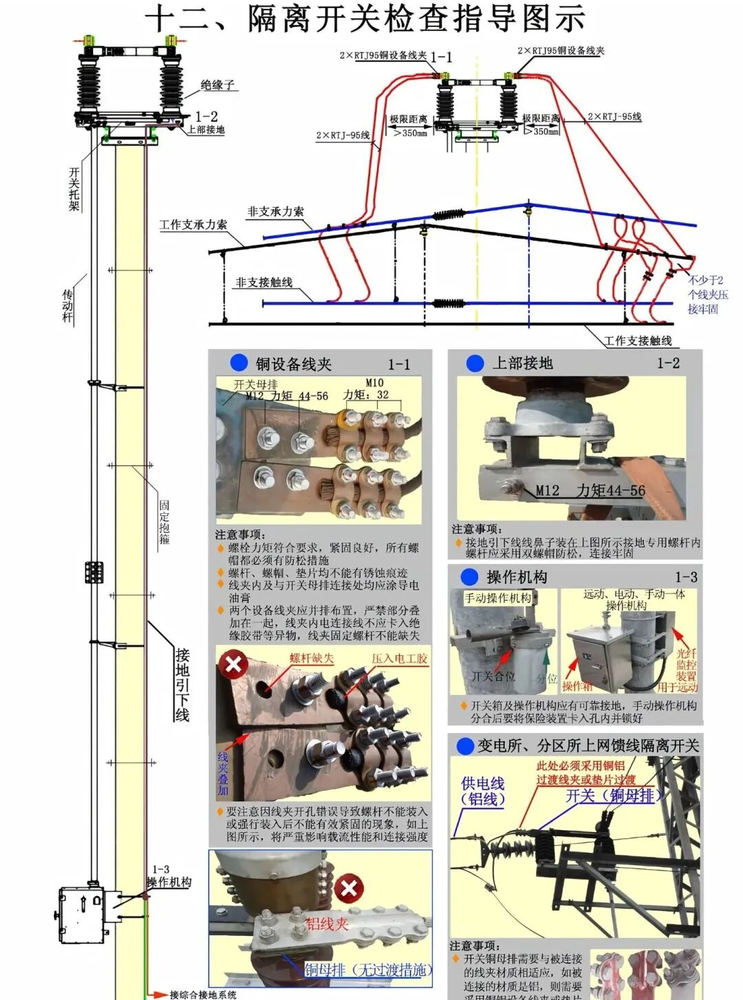
12. Inspection Guide Diagram for Disconnectors (ISOLATING SWITCH)
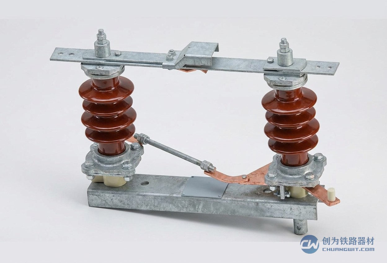
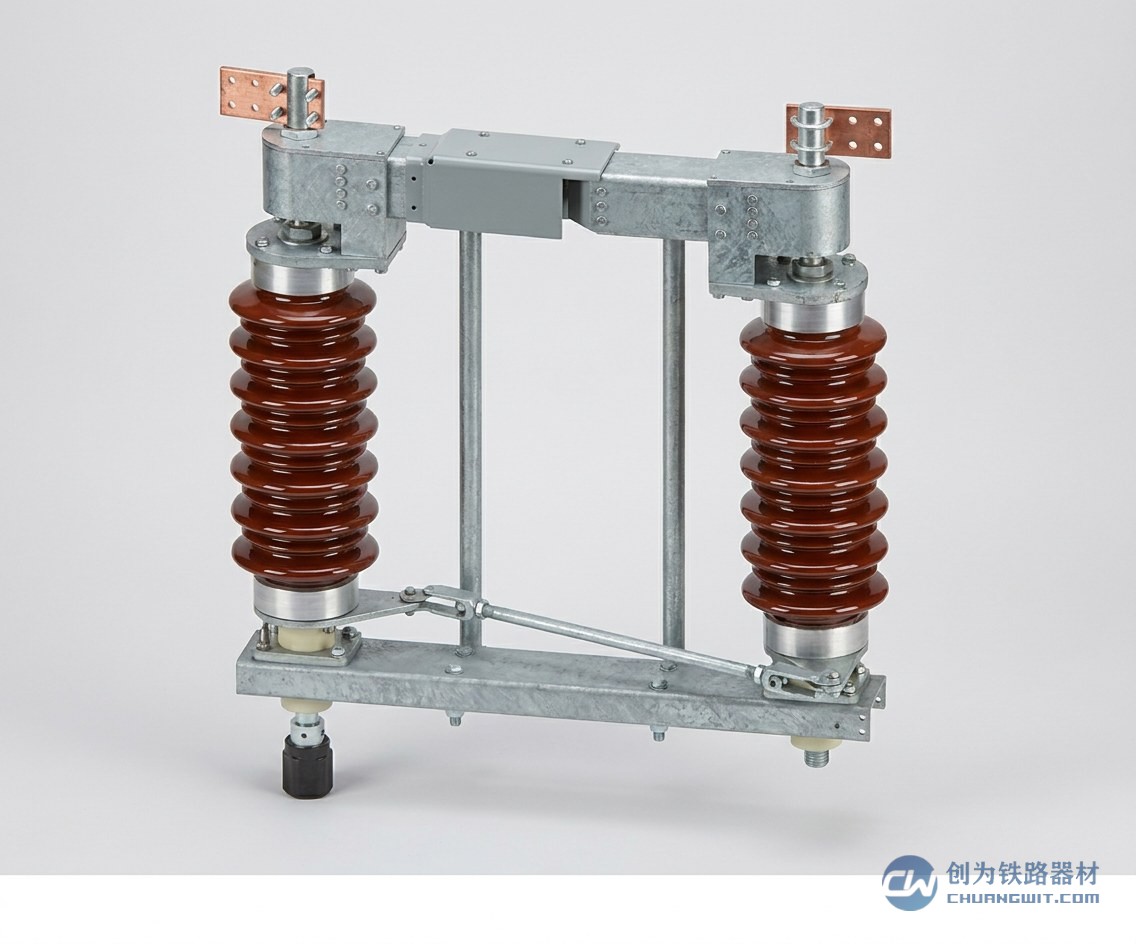
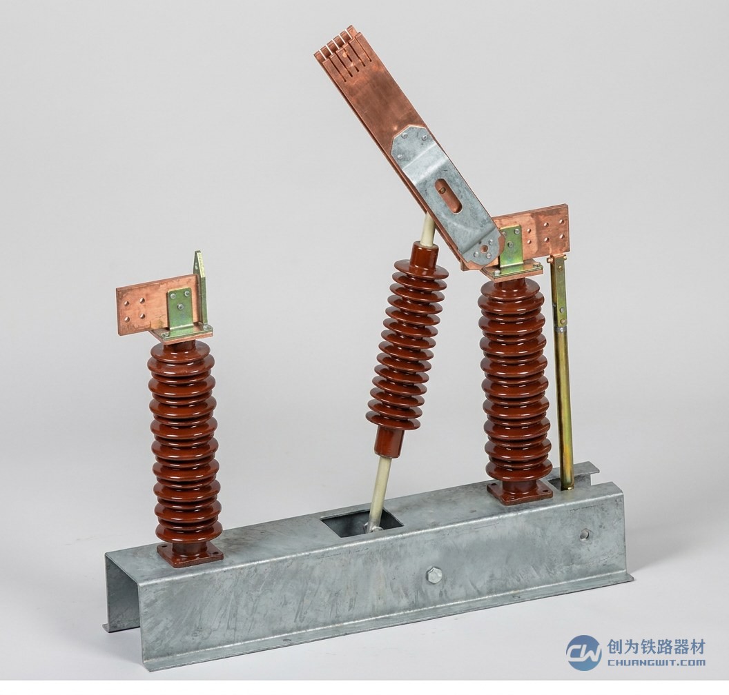
Fig. 12-1 Inspection guide diagram for disconnectors (click to view a larger image)
Key points:The installation of the switch bracket, drive rod, operating mechanism, earthing lead, copper equipment clamp and upper earthing; torque M10=32 N·m / M12=44~56 N·m; a copper-aluminium transition clamp or shim must be used between the copper busbar and the copper connection clamp; the operating mechanism may be of the manual, motor-operated or remote-controlled type.
13. Inspection Guide Diagram for Suction Lines (SUCTION LINE)
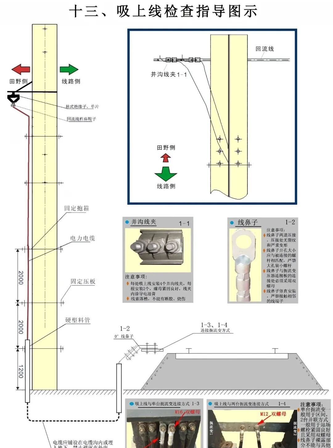
Fig. 13-1 Inspection guide diagram for suction lines (click to view a larger image)
Key points:The installation positions of the suspension insulator, return conductor, truss seat, fixing hoop, power cable, fixing clamp plate and rigid plastic conduit (2000+2000+1200 mm above ground); the installation of the parallel groove clamp and cable lug; the requirements for connecting the suction line to the neutral point of the impedance bond (double nut + spring washer).
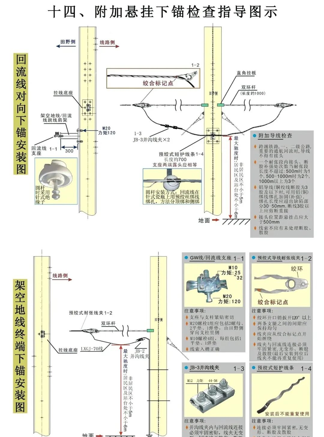
Fig. 14-1 Inspection guide diagram for auxiliary suspension anchors (click to view a larger image)
Key points:The installation of the opposite return conductor anchor and the terminal anchor of the overhead earth wire; the guy wire base, twist marking point, double-eye rod, preformed tension clamp, preformed armour rods and JB-3 parallel groove clamp; the maximum sag (residential area ≥5m, non-residential area ≥4m, station ≥6m); the torque of the GW wire / return conductor support M10=25~32 N·m / M20=120 N·m.
15. Inspection Guide Diagram for Tunnel Embedments and Hanger Posts (TUNNEL EMBEDMENT & HANGER POST)
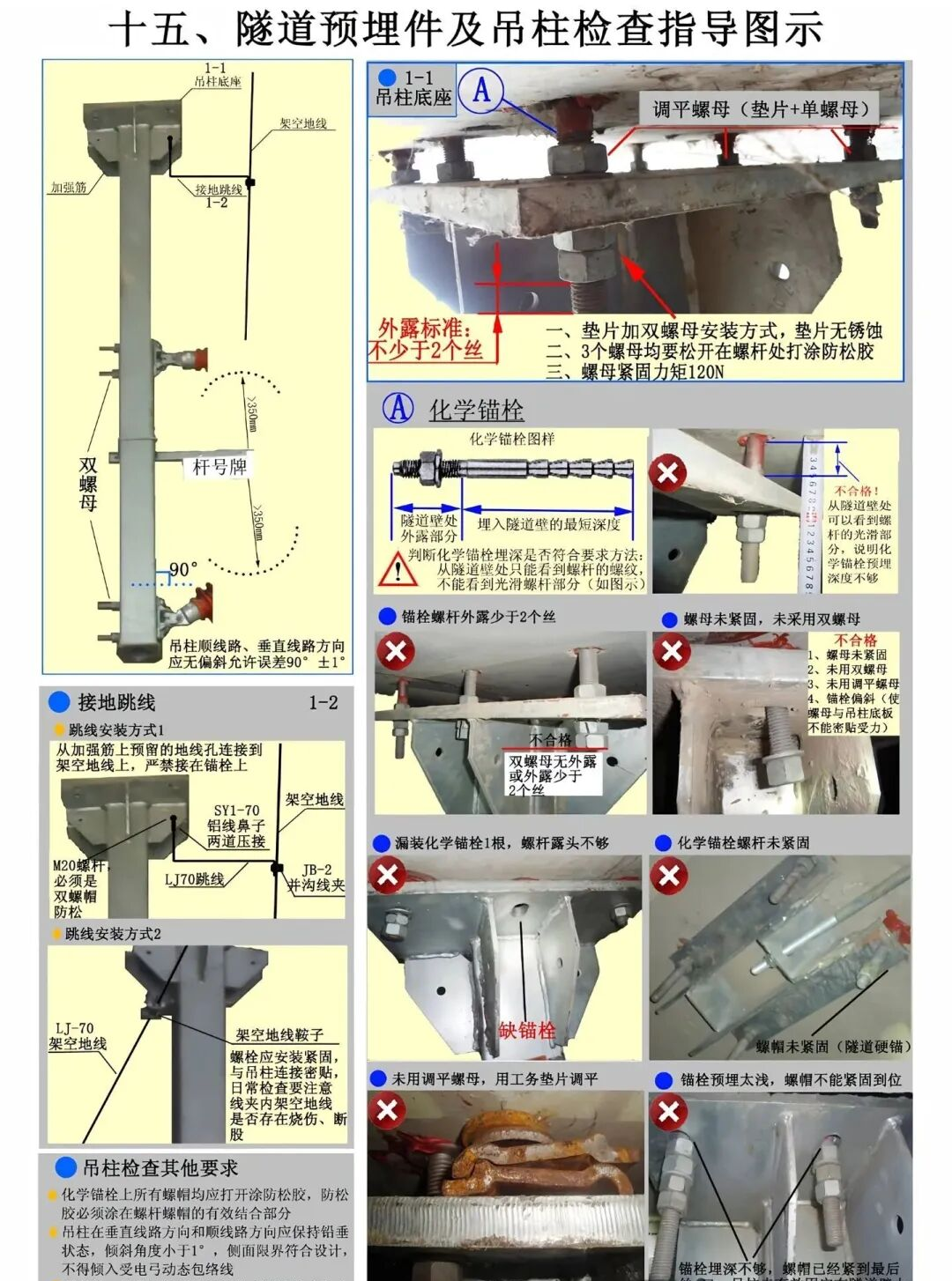
Chemical anchorLevelling nutHanger post baseStandard exposure ≥2 threads
Fig. 15-1 Inspection guide diagram for tunnel embedments and hanger posts (click to view a larger image)
Key points:The embedment depth of the chemical anchor, the standard exposure of ≥2 threads, double-nut locking and the torque of 120N; the levelling nut (shim + single nut); the earthing jumper (method 1 / method 2); the hanger post shall not be skewed either along or perpendicular to the track (tolerance 90°±1°); examples of non-conformance (missing anchor, untightened nut, corroded shim).
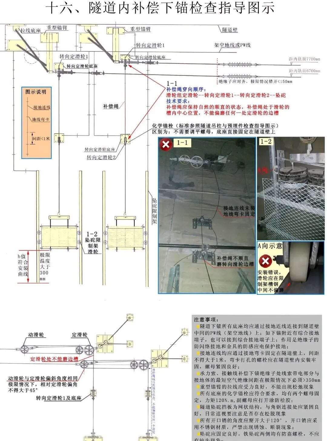
Fig. 16-1 Inspection guide diagram for in-tunnel tensioning anchors (click to view a larger image)
Key points:The routing sequence of the compensation rope (pulley set fixed pulley → deflection fixed pulley 1 → deflection fixed pulley 2 → balance weights); the movable pulley and the fixed pulley shall have the same deflection angle (≤45°); the earthing connection spacing <1m, bend clamp drilled bolt; the torque of the chemical anchor 120N; the balance weights shall be properly secured; 7700/6700mm above the inner rail surface, with a limit offset <150mm.
This album contains inspection guide diagrams for 16 major categories of OCS components, covering the full range of typical scenarios from ground level to tunnels and from support devices to phase separation and sectioning equipment.
Unless stated otherwise, dimensions shown in the diagrams are in mm, torques are in N·m and tensile forces are in N.
Where the bottom right corner of a diagram shows "Fig. X-1 (click to view a larger image)", clicking the image opens the original 1080×1454 high-definition version in a new tab, so that details can be examined on site.
It is recommended to use this album together with the maintenance process documents and the equipment models currently in force in your organisation; where it is inconsistent with the latest regulations, the latest regulations shall prevail.