1. Overview
The traction power supply system of trunk and high-speed railways is the power source for train operation. Its core requirement is to maintain stable, reliable current transfer between pantograph and overhead contact system (OCS) while trains pass at high speed. As operating speeds rise, dynamic pantograph-catenary current collection becomes the key technical bottleneck constraining high-speed railway development — the higher the train speed, the more severe the arcing and contact-loss discharge caused by pantograph sliding, placing higher demands on the elasticity uniformity and tension stability of the OCS suspension. Worldwide, the fully compensated catenary suspension under AT (autotransformer) feeding has become the standard configuration for high-speed railways above 250 km/h and long-distance trunk lines. This combination brings together the advantages of the feeding system and the suspension structure, guaranteeing excellent current-collection quality under high-power traction, long feeding arms and double-pantograph multiple-unit operation.
This document systematically describes the technical principles, system composition, key equipment parameters, advantages and limitations, and typical domestic and international applications of the fully compensated catenary solution under AT feeding, aiming to provide a reference for the design, construction and maintenance of high-speed railway traction power supply systems. Intended readers include traction power supply engineers, OCS designers, construction managers and high-speed railway maintenance technicians.
2. Applicable Scenarios
The fully compensated catenary solution under AT feeding mainly targets the following operating scenarios: high-speed passenger-dedicated lines above 250 km/h, long-distance mixed passenger-freight trunk lines above 160 km/h, and heavy-haul trunk lines with high current-collection quality requirements. In these scenarios, trains run fast and draw large traction currents, imposing stringent requirements on the dynamic response and supply stability of the pantograph-OCS system.
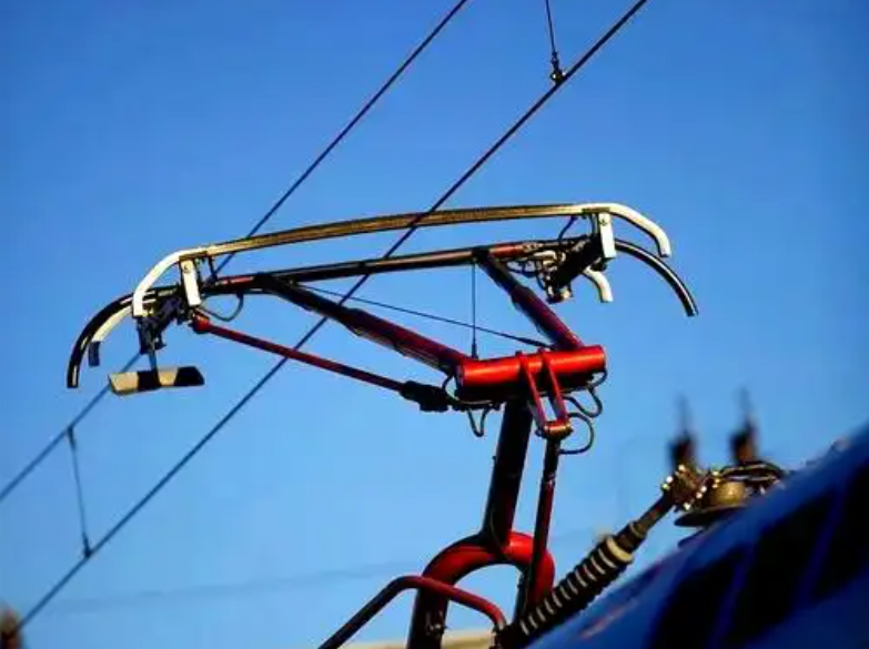
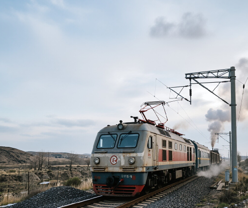
In passenger-dedicated line scenarios, whether trains collect current with one pantograph or two, the amplitude of contact-force fluctuation between pantograph and OCS directly affects current-collection quality. Research shows that when train speed approaches 70% of the OCS wave speed, the dynamic response deteriorates significantly, contact-force fluctuation increases sharply and the contact-loss rate rises substantially. High-speed lines must therefore adopt suspension structures with uniform elasticity and stable tension — exactly what fully compensated catenary provides. For mixed-traffic trunk lines, freight locomotives typically reach traction power above 25 MW; AT feeding can extend the feeding arm to 40-50 km, greatly reducing the number of substations and lowering project cost while keeping supply voltage stable.
| Scenario | Typical Speed | Traction Power | Recommended Feeding |
|---|---|---|---|
| High-speed passenger-dedicated line | 250-350 km/h | 8-12 MW/train | AT feeding + fully compensated catenary |
| Trunk mixed passenger-freight | 160-250 km/h | Above 25 MW | AT feeding + fully compensated catenary |
| Heavy-haul freight trunk | 80-120 km/h | 15-25 MW | AT feeding + fully compensated simple catenary |
| Intercity lines | 160-200 km/h | 4-8 MW/train | Direct feeding or AT + fully compensated simple catenary |
3. Core Technologies
3.1 Feeding System: Single-Phase 50 Hz 25 kV AC AT Feeding
High-speed railways worldwide generally adopt the single-phase 50 Hz 25 kV AC system, which offers significant advantages in technical maturity, economy and reliability. Compared with direct feeding (1x25 kV), the core principle of AT feeding (2x25 kV) is to add a negative feeder (F) between the catenary (T) and the rail (R), with autotransformers (AT) installed every 10-15 km along the line. The AT midpoint connects to the rail, and its two ends connect to the catenary and the negative feeder respectively. In this way, between the substation and the AT post, the catenary and the negative feeder each carry about half the current, the effective transmission voltage is 50 kV, while the train still receives 25 kV.
The direct effects of this mechanism are: line current is reduced to half that of direct feeding; voltage loss and energy loss drop substantially; the feeding arm can be extended to 40-50 km (versus only 20-25 km for direct feeding), reducing the number of substations by about 40%. Meanwhile, because the negative feeder and catenary currents flow in opposite directions, their induced currents in the rail and earth cancel each other, significantly reducing electromagnetic interference with communication lines — vital for the safe operation of signaling systems along high-speed railways. In addition, the all-parallel AT feeding arrangement adds transverse connections between the up and down catenaries, further improving supply reliability and short-circuit protection sensitivity.
| Technical Indicator | Direct Feeding (1x25 kV) | AT Feeding (2x25 kV) |
|---|---|---|
| Feeding arm length | 20-25 km | 40-50 km |
| Line voltage loss | Relatively large | About half of direct feeding |
| Number of substations | More (short spacing) | Fewer (about 40% reduction) |
| Interference with communication lines | Relatively large | Significantly reduced |
| OCS structural complexity | Simple | More complex (adds AF and PW wires) |
| Project cost | More substations but simpler OCS | Fewer substations but more complex OCS |
3.2 Suspension Structure: Fully Compensated Stitched Catenary
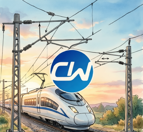
Fully compensated stitched (elastic) catenary is the mainstream suspension form for high-speed railway OCS today. Its structure consists of four parts: messenger wire, contact wire, stitch wires (elastic droppers) and droppers. The messenger is carried at the top of the poles, and the contact wire is suspended below it via droppers and stitch wires, forming a catenary structure. Compared with simple catenary, stitched catenary adds stitch wires between messenger and contact wire; the stitch wire provides additional elastic support near each suspension point, making the contact-wire uplift at the suspension point closer to that at mid-span, thereby significantly improving the elasticity uniformity of the contact wire.
The word "fully" in fully compensated means that both the messenger and the contact wire are equipped with automatic tension compensation devices. When temperature changes cause thermal expansion and contraction, the compensation device automatically adjusts wire tension through counterweight displacement, keeping the wire sag stable over the entire temperature range. This design is especially critical for high-speed railways — changes in contact-wire sag directly affect dynamic pantograph contact force and thus current-collection quality. In northern China, the winter-summer temperature difference can reach 60-70 degrees C; without compensation devices, contact-wire sag would vary by tens of centimeters, making high-speed current collection impossible.
Stitch wire tension is typically 3.5-6 kN, messenger tension 15-25 kN, and contact wire tension 25-30 kN. The stitch wires reduce the uplift difference between suspension points and mid-span from 30-40 mm in simple suspension to 5-10 mm, controlling elasticity non-uniformity within 10%. This improvement is vital to the stability of dynamic contact force at high speed. According to research literature, with stitched catenary the standard deviation of pantograph-catenary contact force at 350 km/h can be controlled within 30 N, while simple catenary at the same speed often exceeds 50 N.
3.3 Key Equipment
3.3.1 High-Strength Copper-Magnesium Alloy Contact Wire
The contact wire is the conductor in direct sliding contact with the pantograph in the pantograph-OCS system; its material properties directly determine current-collection quality and service life. High-speed railways use 150 mm² cross-section copper-magnesium alloy contact wire, the current mainstream choice for high-speed railways worldwide. The magnesium content of copper-magnesium alloy is typically 0.4%-0.7%; its core advantage is combining high tensile strength with good conductivity. Taking the Chinese CTMH150 contact wire as an example, its minimum tensile strength is no less than 440 MPa and conductivity no less than 68% IACS, maintaining good sag characteristics even under tension above 25 kN.
Compared with pure copper contact wire, copper-magnesium alloy increases tensile strength by about 30%, meaning less sag deformation and lower camber at the same tension level, which helps raise the pantograph-OCS wave speed and improve current-collection quality. The higher strength reserve also means stronger wear resistance, withstanding continuous sliding wear from the pantograph at high speed and extending contact-wire life. Japan's Shinkansen uses 110 mm² copper-magnesium contact wire; European high-speed rail mainly uses copper-silver and copper-tin alloys at 100-120 mm²; China's 150 mm² large-section copper-magnesium alloy is among the highest-level configurations in the world.
3.3.2 Integral Bracket Structure
The bracket (cantilever) is the OCS support structure that suspends the messenger and contact wire above the poles. The integral bracket structure used on high-speed railways consists of a horizontal bracket arm and an inclined arm, connected via the messenger seat and sleeve seat to form a rigid triangular frame. Compared with traditional elastic suspension brackets, the integral bracket eliminates messenger sway in operation, provides a more stable support structure, effectively resists crosswind loads and ensures contact-wire position stability.
Bracket pre-assembly is a key step in OCS construction. Modern construction uses intelligent bracket pre-assembly technology, with servo motors and dedicated tooling enabling automatic positioning and installation of components, controlling bracket assembly accuracy within ±1 mm. This precision is essential for contact-wire straightness, because bracket installation errors are transmitted directly to the contact-wire position and affect current-collection quality. In addition, China has recently developed wind-resistant integral steel brackets, specially optimized for strong-wind areas such as coastal and valley regions, raising wind resistance to withstand crosswinds above 30 m/s.
3.3.3 Tension Compensation Devices
The tension compensator is the core component of the fully compensated suspension system; it automatically adjusts wire tension as temperature changes, keeping the sag of contact wire and messenger stable. Current mainstream compensation device types include pulley-block, ratchet and spring compensation. Pulley-block compensation has high transmission efficiency and good tension constancy, but a larger and heavier structure; ratchet compensation is compact and needs little installation space, but demands high manufacturing precision; spring compensation uses spring elements to provide compensating force, with fast response and simple structure, but limited tension travel.
Ratchet compensation devices are the most widely used on Chinese high-speed railways. The principle: an embedded ratchet structure converts thermal expansion of the wire into counterweight displacement, transmitted via wire rope to the conductor, thereby keeping tension constant. For contact wire, the compensation travel is typically 550-850 mm, covering a temperature range from -40 to +80 degrees C. Tension compensation accuracy directly affects contact-wire sag and thus current-collection quality, so installation and adjustment of compensation devices are important steps in OCS construction.
3.3.4 Wind-Resistant Registration Devices
Registration (steady arm) devices hold the contact wire stable at the track centerline, preventing lateral displacement under wind load, centrifugal force and other actions. High-speed railways impose far higher requirements on registration devices than conventional railways, because lateral contact-wire deviation directly affects pantograph current-collection quality and, in severe cases, can cause pantograph-scraping accidents. Modern high-speed railways widely adopt reverse-registration elastic damper support mechanisms, inserting elastic damping elements between the registration arm and the registration tube, which provide sufficient registration force while offering elastic compensation during pantograph passage to reduce impact on the pantograph.
In strong-wind regions such as China's coastal and northwestern wind zones, the OCS also needs dedicated wind-resistant design. Main measures include shortening span length (from the standard 65 m to 50 m), using thickened registration arms and adding wind braces. Shortening spans is the most effective wind-resistant measure because it reduces the wind-exposed area and free length of the contact wire, but it also increases the number of poles and brackets, raising project cost. In practice, special calculations based on local wind-load spectrum data are needed to balance safety and economy.
4. Solution Advantages
4.1 Excellent Current-Collection Quality
The core advantage of fully compensated stitched catenary is its outstanding current-collection quality, reflected in three aspects. First, stable contact-wire sag: the full compensation devices keep contact-wire sag variation within 10 mm over the entire temperature range, far below the tens of millimeters of uncompensated suspension. Second, good elasticity uniformity: stitch wires significantly reduce the elasticity difference between suspension points and mid-span, so the pantograph produces no obvious impact when passing suspension points. Third, high contact-wire straightness accuracy: Chinese high-speed railway construction standards require contact-wire straightness deviation no greater than 0.1 mm/m, with key processes controlled at 0.05 mm/m — among the highest levels worldwide.
Contact-wire straightness control is the foundation of current-collection quality. Research shows that contact-wire irregularities generate high-frequency pantograph-OCS disturbances that couple with pantograph motion, increasing contact-force fluctuation. At 350 km/h operation, every 0.1 mm/m increase in straightness deviation raises the standard deviation of contact force by about 5-8 N. The 0.05-0.1 mm/m straightness target is therefore a necessary condition for keeping the effect of contact-wire irregularity within acceptable limits, achieved through high-precision bracket pre-assembly, dropper calculation and field adjustment processes.
4.2 Double-Pantograph Multiple-Unit Capability
Double-pantograph multiple-unit operation is an important way for high-speed railways to increase capacity: two coupled EMU sets each raise one pantograph for current collection. This poses a severe challenge to the pantograph-OCS system: the leading pantograph excites waves on the contact wire, and when these waves propagate to the trailing pantograph position they change the contact force, degrading the trailing pantograph's current-collection quality. With its higher wave speed and better elasticity uniformity, fully compensated stitched catenary effectively suppresses the influence of leading-pantograph waves on the trailing pantograph.
On Chinese high-speed railways, 16-car EMU sets use double-pantograph current collection with a leading-trailing pantograph spacing of about 200-250 m. Test data show that at 350 km/h in double-pantograph operation, the contact-force standard deviation is about 28 N for the leading pantograph and about 35 N for the trailing pantograph, both within acceptable range. Under simple catenary, the trailing-pantograph standard deviation in the same conditions often exceeds 50 N, with a markedly higher contact-loss rate. This is why fully compensated stitched catenary is a prerequisite for double-pantograph operation at high speed — it provides the higher wave speed and better dynamic response that double-pantograph running requires.
4.3 Mature Lightning and Strong-Wind Protection Design
High-speed railway OCS operates in the open air, where lightning strikes and strong winds are the two main natural threats. For lightning protection, the AT feeding system itself offers certain advantages. Because the voltage between catenary and negative feeder is 25 kV and the catenary-to-earth voltage is also 25 kV, lightning voltage is distributed more evenly between catenary and negative feeder, reducing the probability of insulator flashover. High-speed railway OCS also adopts dedicated lightning protection measures, including surge arresters at key nodes such as substations, sectioning posts and AT posts, and overhead ground wires in areas of frequent lightning activity.
For wind protection, high-speed railway OCS design has accumulated rich engineering experience. China's coastal high-speed lines (such as Beijing-Shanghai and Shanghai-Kunming) and northwestern wind-zone lines (such as Lanzhou-Xinjiang and Harbin-Dalian) all use dedicated wind-resistant designs, mainly shorter spans, wind-resistant brackets and registration devices, and wind braces. The design generally takes a basic wind speed of 30 m/s and an operating wind speed of 20 m/s as the standard, with special calculations based on measured wind speeds for particular locations. Years of operation have shown that these wind-resistant designs perform well in service, effectively ensuring operational safety under strong winds.
5. Limitations and Countermeasures
Despite its significant advantages, the fully compensated catenary solution under AT feeding has some non-negligible limitations. First, AT feeding makes the OCS structure complex: two additional conductors (AF and PW wires) must be suspended on the field side, increasing pole loading and construction difficulty as well as failure probability. When an OCS fault occurs — especially a pole-break accident — restoration takes longer and affects operations more severely.
Second, the construction process of fully compensated stitched catenary is complex and demands extremely high precision. Stitch-wire installation positions, tension values and dropper lengths must all be precisely calculated, and any deviation affects contact-wire sag and elasticity uniformity. Compared with simple catenary, stitched catenary construction takes about 15-20% longer and demands higher technical skill from the construction team. In addition, full compensation devices require considerable maintenance: regular checks of compensator flexibility, wire-rope wear and pulley-block lubrication.
Third, in tunnels and urban areas the advantages of AT feeding are hard to realize fully. Tunnel space is limited, making installation and maintenance of additional conductors difficult; urban station areas have many parallel tracks, making the OCS structure even more complex. Countermeasures include: promoting intelligent construction technology to reduce dependence on manual precision; developing online OCS monitoring systems for early fault warning; and combining rigid and flexible suspension in tunnels to simplify the structure.
6. Typical Applications
6.1 Chinese High-Speed Rail: Beijing-Shanghai and Wuhan-Guangzhou Lines
China's high-speed railway is the largest high-speed network in the world, with operating mileage exceeding 40,000 km, the vast majority of trunk lines using AT feeding and fully compensated catenary suspension. The Beijing-Shanghai high-speed railway is China's most representative high-speed line, designed for 350 km/h over its full 1,318 km. Its traction power supply uses the all-parallel AT feeding arrangement; the OCS uses fully compensated simple catenary suspension; the contact wire is CTMH150 copper-magnesium alloy at 30 kN tension, with messenger tension of 20 kN. In the comprehensive tests before opening, the train reached a maximum test speed of 486.1 km/h with stable pantograph-OCS current-collection performance, fully verifying the reliability of the solution.
The Wuhan-Guangzhou high-speed railway was among China's first 350 km/h high-speed lines, with a full length of 1,069 km. Its traction power supply likewise uses AT feeding and the OCS uses fully compensated catenary suspension. The line is distinctive in crossing complex terrain such as the Nanling mountains, with numerous tunnels along the route, placing higher demands on OCS lightning protection and structural stability. Its successful construction and operation have accumulated valuable experience for high-speed railway traction power supply design under complex terrain, forming a mature set of technical standards especially for in-tunnel OCS construction and lightning protection earthing.
6.2 Japan's Shinkansen
Japan's Shinkansen is the world's earliest high-speed railway system, accumulating more than 60 years of operating experience since the Tokaido Shinkansen opened in 1964. The Shinkansen uses compound catenary suspension, a three-wire structure composed of an auxiliary messenger, a main messenger and the contact wire. This structure excels in pantograph-OCS elasticity uniformity, effectively suppressing OCS vibration, and together with high-strength copper-tin alloy contact wire supports stable operation at the 300 km/h level. The Shinkansen's experience in miniaturized, lightweight and high-reliability OCS component design has also provided a useful reference for the technical development of China's high-speed railway catenary.
Related equipment: AT-fed catenary is divided into maintenance and isolation sections by the same hardware as any 25 kV AC overhead contact system - see the Chuangwit section insulator range for Type A and Type B designs to TB/T 3036-2016.