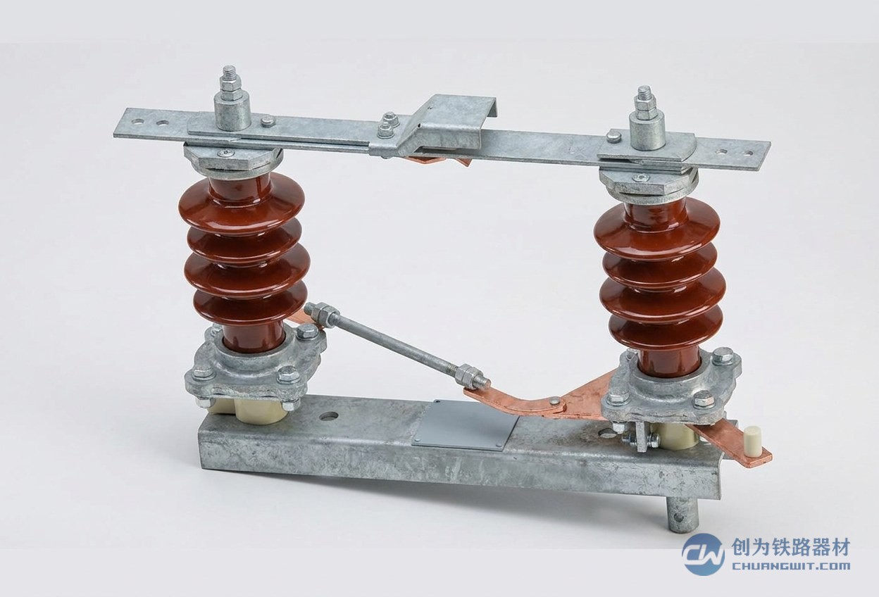
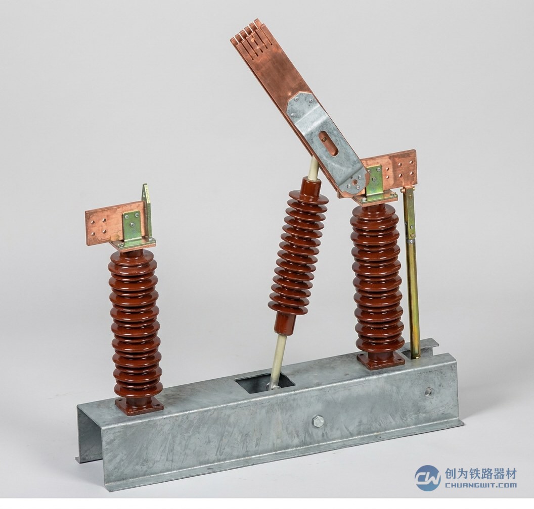
The 27.5kV disconnector is key equipment for circuit isolation and switching operations in the traction substations and overhead contact systems of electrified railways, and its condition bears directly on the reliability of traction supply and on traffic safety. Exposed outdoors for long periods, disconnector contacts oxidise and collect contamination, drive components gradually wear and the surfaces of insulators accumulate pollution; without proper maintenance this can develop into overheating of contacts, incomplete opening or closing, or even insulation flashover. Drawing on practice generally accepted in the railway OCS industry, this article sets out systematically the main content of 27.5kV disconnector maintenance and the reasoning behind the judgements, for the reference of power supply depots, operating units and technical staff. It should be emphasised in particular that the maintenance intervals and the various acceptance values mentioned here are governed by the maintenance regulations of the operating company and by the product technical conditions, and must not be applied mechanically without regard to the actual line and equipment concerned.
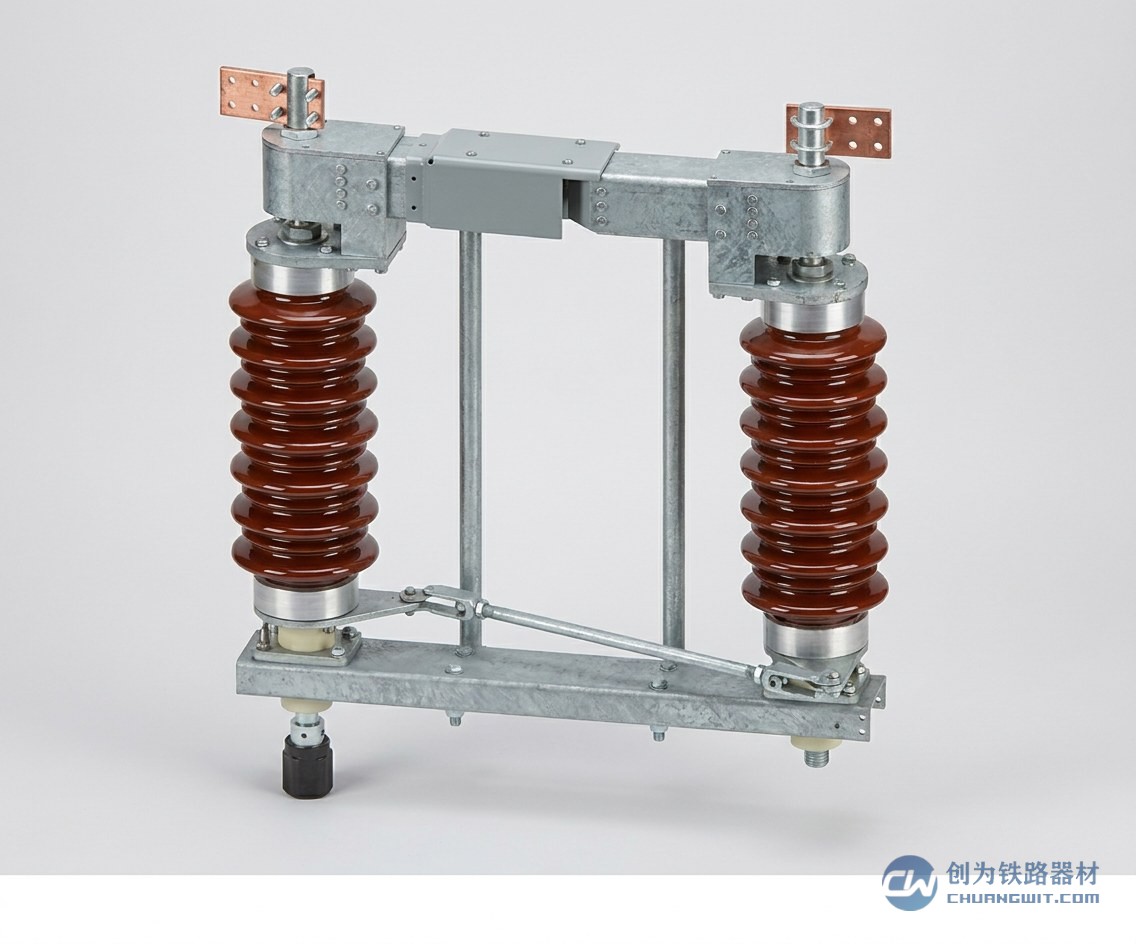
Classification of Maintenance: Routine Patrol, Scheduled Maintenance and Condition-Based Maintenance
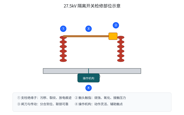
Under the equipment management approach currently applied in railway power supply systems, maintenance of a 27.5kV disconnector is generally organised in three tiers which complement one another and together form a complete equipment health management system.
- Routine patrol: theroutine checks carried out by operating staff on site or through telecontrol monitoring, focusing on the appearance of the equipment, abnormal heating and discolouration at the contacts, damage and discharge traces on insulators, and corrosion or jamming of the operating mechanism. Any abnormality found during patrols should be recorded promptly and entered into the defect management process for tracking through to closure.
- Scheduled maintenance: planned maintenance arranged under the maintenance regulations of the operating company, usually carried out within a de-energised possession, covering inspection and cleaning of contacts, measurement of loop resistance, lubrication and adjustment of the drive mechanism, and re-tightening of fasteners. The specific intervals and division of work are governed by the maintenance regulations published by each operating company.
- Condition-based maintenance: an approach in which equipment condition is assessed from monitoring data, live-line testing and patrol and maintenance records before maintenance is arranged, avoiding both over-maintenance and missed maintenance that fixed intervals can bring. The concept has been gradually extended in railway power supply systems in recent years, its essence being to let the maintenance plan follow the condition of the equipment rather than the calendar.
Whichever approach is adopted, the safety measures of isolation, voltage testing and application of earths must be strictly implemented before work begins, and acceptance formalities must be completed afterwards so that the equipment is confirmed ready for energisation before the possession is given up.
Contact Inspection and Cleaning: Removing Oxide and Applying Contact Grease
The contacts are the core component through which a disconnector carries load current, and they are the part that takes the most work and the most care in 27.5kV disconnector maintenance. Contacts in outdoor service are exposed to the atmosphere for long periods, and an oxide film forms on the surface with dust, salt and other contamination adhering to it, increasing contact resistance and causing heating in service. Contact inspection and cleaning should concentrate on the following points:
- Removing oxide: for the oxide film and slight arc erosion on conductive contact surfaces such as contact fingers and contact seats, it is preferable to polish lightly with fine abrasive cloth or a purpose-made tool working along the direction of the contact surface, and then to wipe the surface clean with a clean cloth. Polishing should avoid damaging the surface plating or altering the geometry of the contact surface; contacts with severe erosion, obvious weld beads or loss of plating should be assessed for replacement against the product technical conditions.
- Applying contact grease: once the contact surfaces have been cleaned, a thin and even layer of electrical contact grease may be applied as specified, to improve the contact condition and prevent re-oxidation. The quantity applied should be moderate, since an excessively thick layer may affect contact pressure and heat dissipation; the detailed requirements follow the product technical conditions.
- Checking contact pressure and contact position: check the contact finger springs for fatigue, corrosion or fracture, and check that after closing the contact position is centred and the contact depth meets requirements. The relative position of the two contacts and the gap after opening - that is, the 27.5kV disconnector contact gap - bear directly on opening and closing performance and on insulation safety, and adjustment should be made to the condition specified in the product manual and the product technical conditions.
During contact inspection, the area around the contacts should also be checked for discolouration left by abnormal temperature rise. Such traces are often a direct indication of poor contact and can corroborate the results of loop resistance measurement.
Loop Resistance Measurement: Comparison Against the Factory Measured Value
Loop resistance is an important indicator of the condition of a disconnector's conductive circuit. During maintenance, with the unit closed, the resistance of the whole conductive loop is normally measured with a loop resistance tester using the DC voltage drop method. It should be emphasised that there is no universal fixed figure by which loop resistance can be judged normal, and the correct approach is to compare against the factory measured value and the product technical conditions:
- If the measured result shows no obvious increase over the factory value and the poles are well balanced against one another, the conductive loop may be considered to be in normal condition.
- If the measured value shows an obvious increase over the factory value, first eliminate factors in the measurement itself such as test connections and poor contact of the test clamps, then check whether the contact surfaces have oxidised, whether contact finger pressure has fallen and whether fasteners at the conductive joints have loosened.
- For a loop that remains obviously high when re-measured after cleaning the contacts and re-tightening the connections, the judgement should be made together with the temperature rise records and the visual inspection, and the contact assembly replaced where necessary, or the manufacturer consulted to confirm the treatment.
The so-called 27.5kV disconnector loop resistance standard should therefore be understood correctly: the acceptance basis for each unit comes from that unit's own factory test report, and the criteria come from the maintenance regulations of the operating company and the product technical conditions. Operating units are advised to keep a measurement record for each unit, logging the measured data and the ambient temperature each time, so that early signs of deterioration in the conductive loop can be detected by comparing trends over time. This is also an important data foundation for condition-based maintenance.
Drive and Interlock Checks: Full Travel and a Reliable Operating Mechanism
The reliability with which a disconnector opens and closes depends on the good condition of the drive system and the operating mechanism. During maintenance, manual or motorised operating tests should be carried out and the following checked item by item:
- Full travel: after closing, the contacts are fully engaged with no poor connection; after opening, the specified gap is reached and sufficient insulation clearance is maintained between the two contacts. The position indicated by the open/closed indicator should agree with the actual condition of the contacts.
- Free operation of the mechanism: all rotating parts of the mechanism are properly lubricated and free from binding, and the operating torque is normal without sudden jumps. The control circuit of a motorised mechanism operates correctly, the auxiliary switches change over reliably and the limit switches act accurately.
- Reliable interlocks: mechanical and electrical interlocks operate correctly and effectively prevent maloperation such as opening or closing under load. Interlock testing should be confirmed item by item at acceptance and must not be replaced by a check by feel.
- Tight connections: pins and bolts at drive rods, crank arms and bases are complete and tight, split pins are intact and in place, welds are free from cracks, and bearing and bush wear is within the permitted range.
Cleaning Insulating Parts, Pollution Level Management and Checks on Leads and Earthing
Insulation performance is the other lifeline of safe operation for a 27.5kV disconnector. Pollution on the surface of outdoor insulators can cause pollution flashover in damp weather such as fog, dew, rain or snow, so cleaning and maintenance must be arranged in conjunction with pollution level management.
- Cleaning insulating parts: remove dirt from the surface of porcelain and composite insulators with a dry cloth or by a method permitted by the regulations, and check the sheds for damage, cracks, ageing, chalking and traces of electrical erosion. The frequency of cleaning follows the arrangements set by the operating company on the basis of local pollution levels and operating experience.
- Pollution level management: the degree of atmospheric pollution varies considerably between sections, so disconnectors in heavily polluted areas should be given more frequent patrols and cleaning, and where necessary the operating company should be consulted so that an insulation configuration suited to the polluted environment can be adopted at the selection stage.
- Checks on leads and earthing connections: check that the clamps on the equipment leads are tight and that the conductors have no broken or splayed strands; that the lead sag is appropriate and the clearances to earth and between phases meet requirements; and that the earthing connection of the equipment is complete, tight and free from serious corrosion, with the earthing circuit conducting properly. The earthing connection may look unassuming, but it is a key element in protecting both people and equipment, and no maintenance should omit it.
Frequently Asked Questions
How often should a 27.5kV disconnector be maintained?
There is no single answer to the maintenance interval. It should follow the maintenance regulations and product technical conditions of the operating company concerned, and be adjusted dynamically in the light of the pollution level of the line, the local climate, the frequency of operation and the history of defects. Organisations that have adopted condition-based maintenance use the result of the condition assessment as the basis for timing maintenance rather than applying a fixed interval mechanically.
What loop resistance counts as acceptable, and is there a specific 27.5kV disconnector loop resistance figure?
Products of different models and from different manufacturers differ considerably in construction, so no universal fixed acceptance figure exists. The correct approach is to compare against the measured value in the factory test report for that particular unit: where the measured value shows no obvious increase and the poles are balanced, the loop is considered normal. The detailed criteria are governed by the maintenance regulations of the operating company and by the product technical conditions. Where the data show an obvious increase, the cause should be investigated and the measurement repeated for confirmation.
What should be done if the gap between the contacts after opening is too small?
An insufficient gap between the contacts after opening is usually connected with incorrect adjustment of the drive mechanism, worn components or installation deviation. The drive should be inspected with the supply isolated and components such as crank arms and pull rods readjusted by the method specified in the product manual, so that the opening gap and the contact condition on closing both meet the product technical conditions. After adjustment an opening and closing test should be carried out and correct interlock operation confirmed.
What causes heating and discolouration at the contacts, and how is it dealt with?
Common causes include oxidation and contamination of the contact surfaces, reduced pressure in the contact finger springs, a displaced contact position and loose connecting fasteners. The approach is to isolate the equipment, clean the contact surfaces and apply contact grease as specified in the technical conditions, check and replace failed springs, re-tighten the connections and then measure the loop resistance and compare it with the factory measured value, so that the conductive loop is confirmed restored before the unit is returned to service.
Proper maintenance is the foundation for extending the service life of a 27.5kV disconnector and for keeping traction supply reliable. Operating units are advised to take the OCS maintenance regulations as their framework and to combine them with the concept of condition-based maintenance to establish a record-based equipment management system, so that every maintenance action is supported by evidence and leaves a traceable record. Henan Chuangwit Railway Equipment Co., Ltd. is a CRCC-certified manufacturer of OCS disconnectors, and its high-voltage disconnector series covers a range of installation and operating arrangements for 27.5kV AC traction supply systems, providing operating units with product selection, technical documentation and maintenance support. You are welcome to find out more through our website.