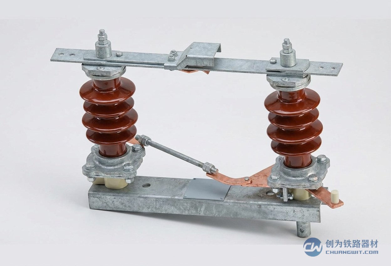
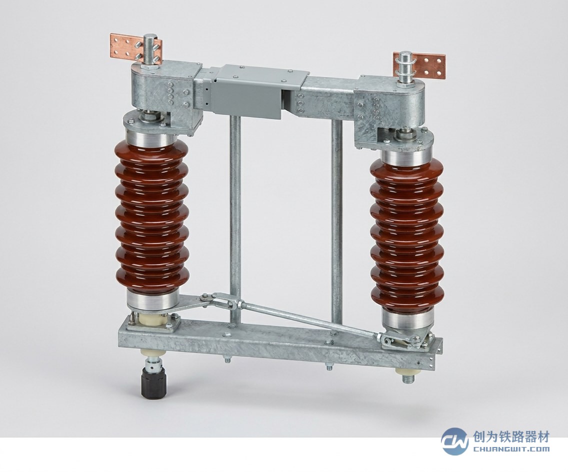
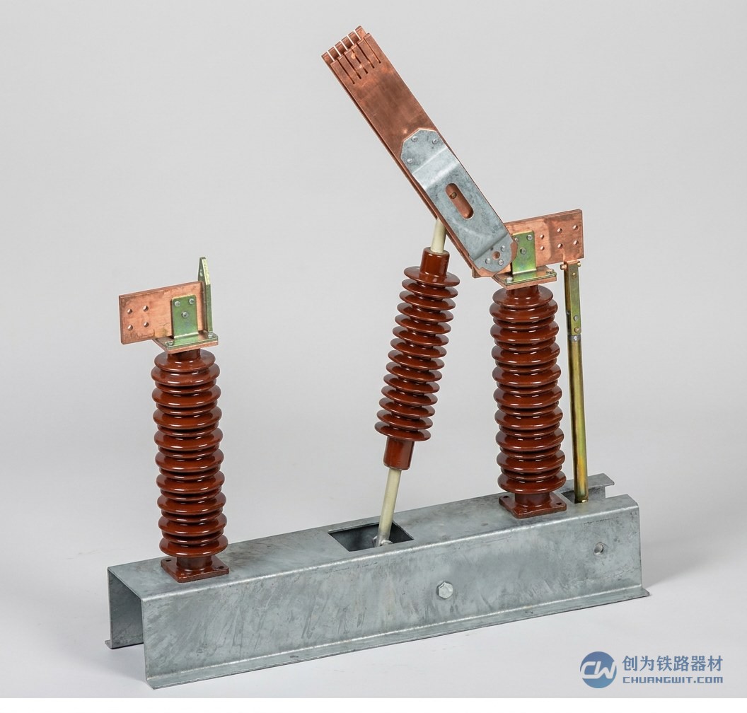
Abstract
Section insulators are the key devices that provide electrical sectioning in the overhead contact systems of electrified railways and urban rail transit. They are installed between two adjacent OCS sections, isolating them electrically while keeping them mechanically continuous. This document systematically sets out the functional role of section insulators, the rigid/flexible suspension classification, the internal structure and working principle, field inspection and adjustment procedures, analysis of common failure mechanisms, and the "restore traffic first, repair afterwards" emergency repair plans. Together with field photographs and a quick-reference table of key parameters, it can serve as daily study and training material for OCS maintenance personnel.
Keywords: section insulator; overhead contact system; rigid suspension; flexible suspension; inspection and adjustment; pantograph-catenary arcing; emergency repair
1. Functional Overview of Section Insulators
1.1 Definition of the Equipment
A section insulator is a dedicated insulating device installed in the overhead contact system of an electrified railway or urban rail transit line. It isolates two adjacent OCS sections electrically while keeping them mechanically connected. Electrical sectioning of the OCS is achieved by means of it, which facilitates power supply dispatching as well as inspection and maintenance.
1.2 Core Functions
Adjacent OCS sections are isolated from one another electrically, giving independent control of different feeding sections and improving the reliability and flexibility of OCS operation.
They are frequently used together with disconnectors: opening or closing the disconnector de-energises or energises an isolated OCS section.
Under normal conditions the pantograph can slide across the section insulator while energised without affecting normal train operation, achieving "seamless passage".
When a fault or a construction-related outage occurs on one OCS section, the disconnector at the sectioning point can be opened to de-energise that part while the rest stays in normal service.
2. Classification of Section Insulators
Depending on the OCS suspension type, section insulators fall into two main categories, rigid suspension and flexible suspension, and each of them can be further subdivided according to the number of contact wires.
2.1 Rigid Suspension Section Insulators
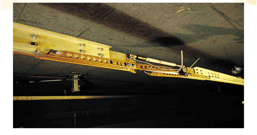
They are installed by inserting them into the conductor rail and the contact wire; once installed, the section insulator and the rigid suspension can move as a whole, which makes them suitable for rigid suspension sections such as metro tunnels.
2.2 Flexible Suspension Section Insulators
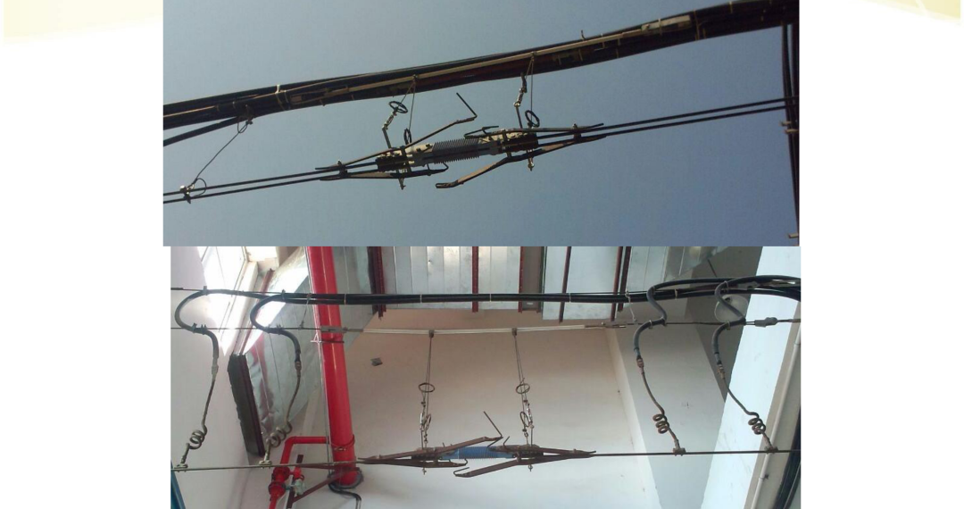
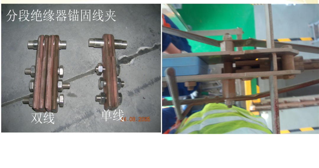
According to the number of contact wires they are divided into double-wire and single-wire types, each with its own installation locations and methods:
| Type | Installation location | Main function |
|---|---|---|
| Double-wire section insulator | Locations where double contact wires and double messenger wires are suspended on depot entry and exit lines | Provides electrical sectioning between depot and main line OCS; the pantograph can pass in both directions |
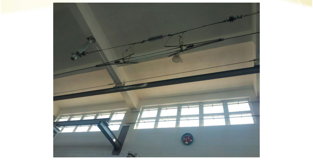
| Single-wire section insulator | Crossover tracks, between the individual feeding sections of a depot, and single contact wire locations inside depot stabling and inspection sheds and maintenance sheds | Provides electrical interconnection and access for maintenance; the pantograph can pass in both directions |
2.3 Two Installation Methods for Flexible Suspension
The section insulator body is inserted into the contact wire, and an insulating rod is installed in the messenger wire.
Installed at the suspension point; the section insulator body is inserted into the contact wire, and an insulating rod is installed in the dropper cable.
3. Internal Structure and Working Principle
3.1 Structural Overview
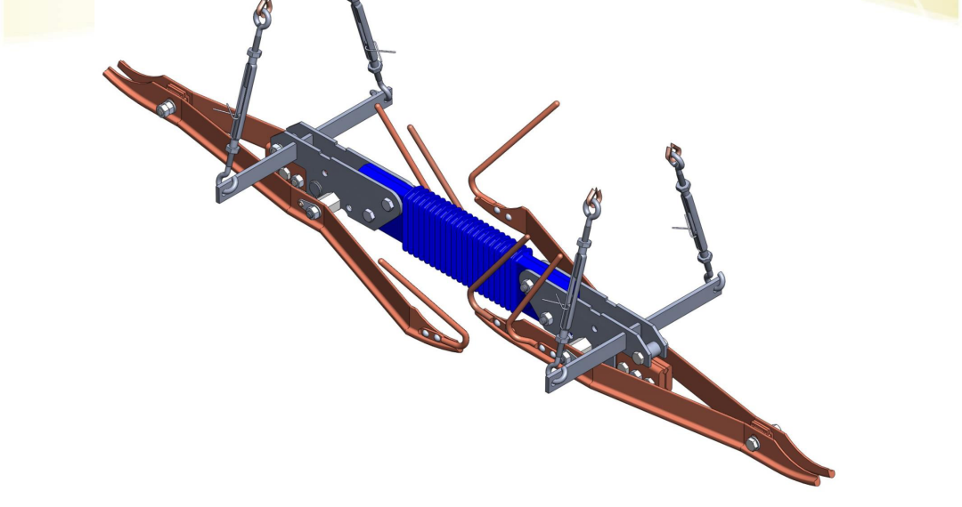
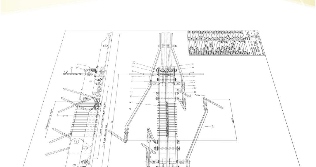
A section insulator is made up of the section insulator body, the messenger wire insulating element (or the dropper insulating element), connecting fittings and suspension accessories. The insulating elements consist of insulating material and metal fittings.
3.2 Main Components
Made of composite material (fibreglass core rod sheathed in silicone rubber) with a shed profile; performs the core electrical isolation function.
Copper slide plates that the pantograph contacts as it passes, ensuring smooth current collection; the upturned ends guide the pantograph in and out.
Curved metal rods that divert the arc to this point so that it is extinguished there, protecting the main insulator from being burnt.
Steel or aluminium alloy clamping plates and connecting fittings with turnbuckles, used for suspension fixing and height adjustment.
3.3 Field Photographs
3.4 Structural Requirements
| Item | Technical requirement |
|---|---|
| 1) Arc-quenching capability | The structure of the section insulator shall have arc-quenching capability. The slideway and insulating parts of an arc-quenching section insulator shall not be burnt or damaged by the arc. |
| 2) Flatness and passage | The lower wear surface of the section insulator shall be flush, and no feature liable to damage the pantograph carbon strip shall be present; installation in curved sections shall not cause pantograph strike either. |
| 3) Section consistency | The cross-section of the conductor rail supplied with the section insulator shall be identical to that of the conductor rail used for normal suspension. |
| 4) Connection strength | The clamps connecting the section insulator to the contact wire or messenger wire shall not slip on the wire at 3 times the rated tension of the wire. |
| 5) Degree of freedom | Once installed, the section insulator shall be free to move with the contact wire so as to accommodate the displacements caused by thermal expansion and contraction. |
3.5 Connection between the Body and the Contact Wire
4. Inspection and Adjustment of Section Insulators
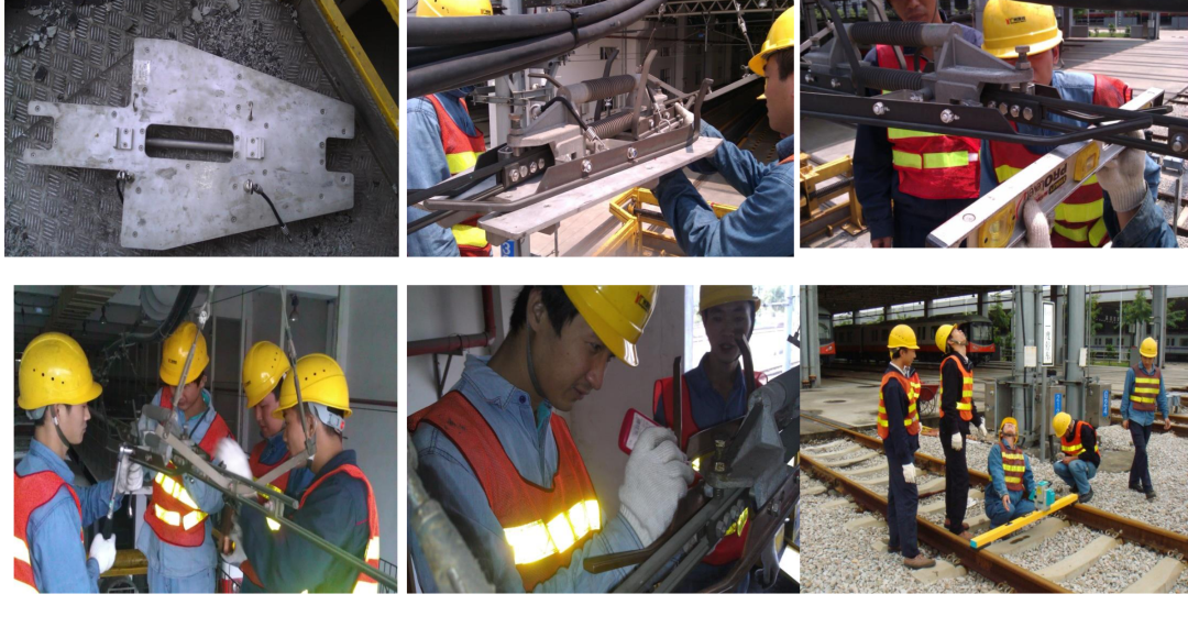
4.1 Inspection Tools and Work Scenarios
In the adjustment and maintenance of section insulators, tools such as a spirit level, a setting plate dedicated to section insulators and a laser contact wire height meter are used to adjust the individual conductive slide plates.
4.2 Key Installation Height Parameters
(1) Measuring the position of the section insulator relative to the track centre
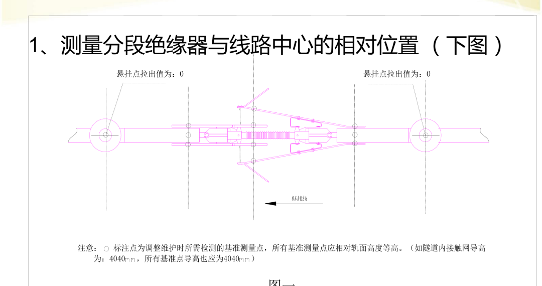
The stagger at both suspension points of the section insulator is 0 (that is, it is installed centrally) and the direction of travel of the vehicle follows the track centre. All reference points marked with a circle must be at the same height.
(2) Measuring the height of the section insulator and its level with the rail surface
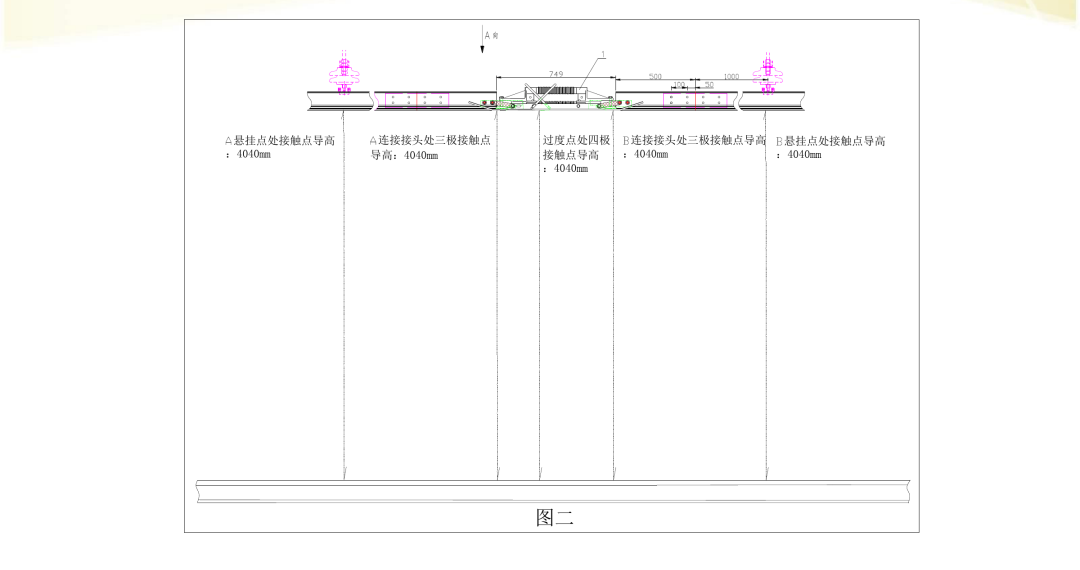
From the suspension points to the centre of the section there are 5 key measurement points, all of which shall have a contact wire height of 4040 mm:
- Contact wire height at the contact point of suspension point A: 4040 mm
- Contact wire height at the three-pole contact point of connection joint A: 4040 mm
- Contact wire height at the four-pole contact point of the transition point: 4040 mm
- Contact wire height at the three-pole contact point of connection joint B: 4040 mm
- Contact wire height at the contact point of suspension point B: 4040 mm
4.3 Installation and Inspection Requirements
Use a torque wrench to check the joints between the section insulator and the contact wire. Where a section insulator is suspended, the connection between the conductive slide plates and the contact wire shall be smooth, all fasteners shall be complete and the connections firm and reliable. Set the torque wrench to 50 Nm and tighten all bolts once. All parts of the section insulator that come into contact with the pantograph working surface shall be parallel to the line joining the rail surfaces; when a spirit level is moved to and fro across the slide plates on both sides of the section insulator and the contact wire, the transition shall be smooth, with no sticking and no eccentric wear, so that the pantograph does not strike in either direction of travel.
4.4 Inspection Notes
- For rigid and flexible suspension OCS, the slide plates on both sides of the section insulator shall wear evenly, and the distance between the two pole shoes shall be 55 mm with a tolerance of ±2 mm.
- For rigid and flexible suspension OCS, the section insulator as a whole shall be parallel to the rail surface (measured at the joint clamps at both ends of the section insulator); its centre point shall be directly above the track centre line, and the deviation of the centre point from the track centre line shall not exceed 50 mm.
- The distance from a rigid section insulator to the adjacent suspension location point shall meet the design requirements, with a permissible deviation of ±200 mm.
4.5 Height Adjustment Criteria
| Suspension type | Height of the joints at both ends | Initial contact point of the slide plate | Overall condition |
|---|---|---|---|
| Flexible suspension | 20~30 mm higher than the normal contact wire height | Level with the rail surface | Parallel to the rail surface; if the height is incorrect, adjust the dropper adjuster |
| Rigid suspension | Level with the normal contact wire height | Level with the normal contact wire height | Parallel to the rail surface |
5. Analysis of Common Section Insulator Failures
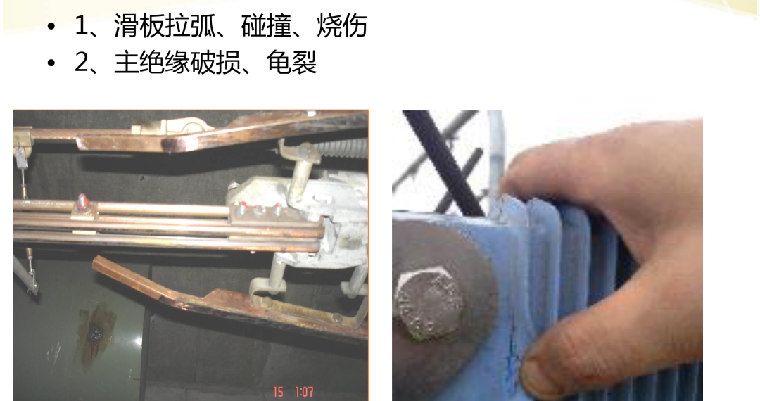
5.1 Common Failure Types
Wear and burning appear on the contact surfaces between the conductive slide plates and the pantograph as a result of mechanical impact or electric arc action.
Cracks appear in the insulator (the shed section), reducing the insulation performance and, in severe cases, causing puncture.
5.2 Analysis of Arcing at the Section Slide Plates
(1) Ideal running condition
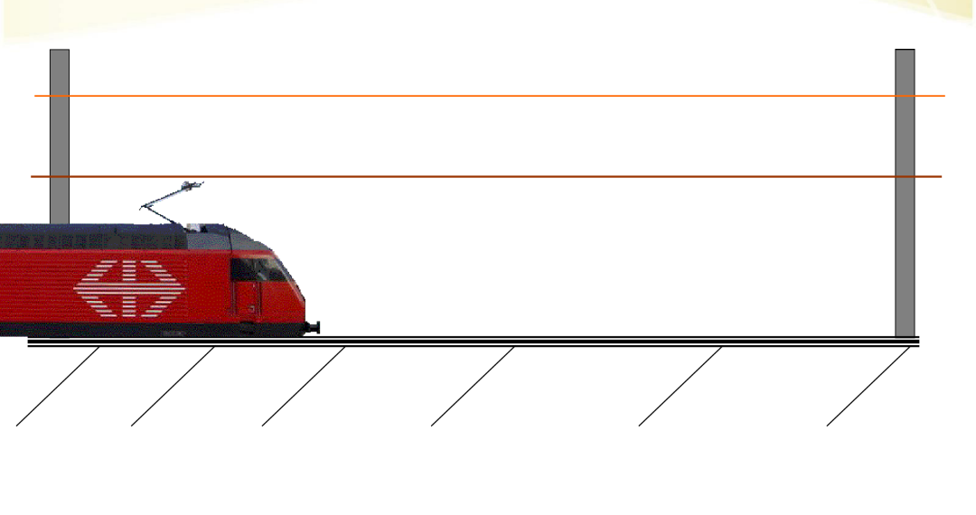
The contact between the pantograph carbon strip and the contact wire is smooth, no arc is produced at all, and current transmission is continuous.
(2) Normal pantograph-catenary condition
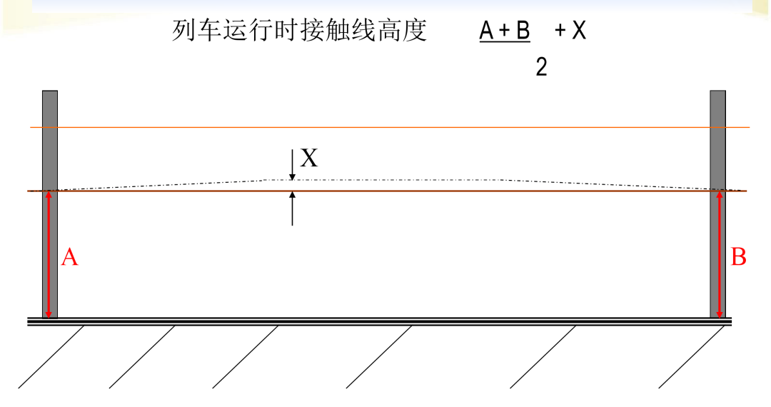
The formula for the contact wire height while the train is running is (A + B) / 2 + X, where X is the pantograph uplift at mid-span.
(3) Height at which the section insulator shall be installed
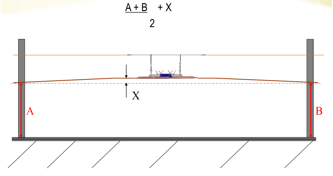
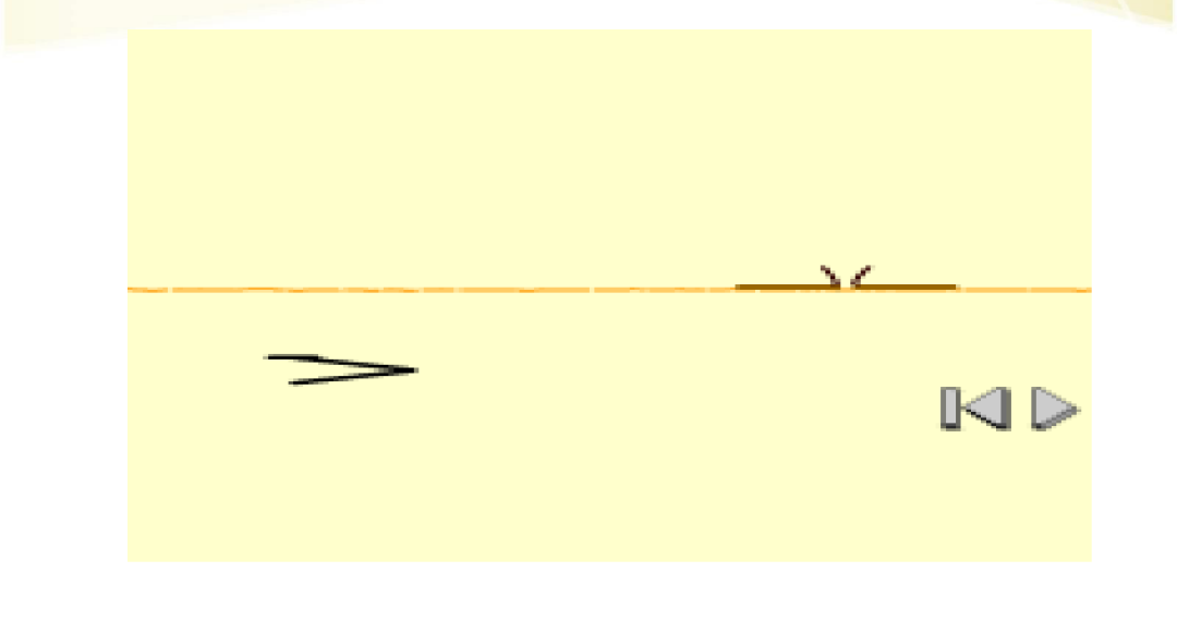
(4) Section not raised - pantograph strike and arcing occur
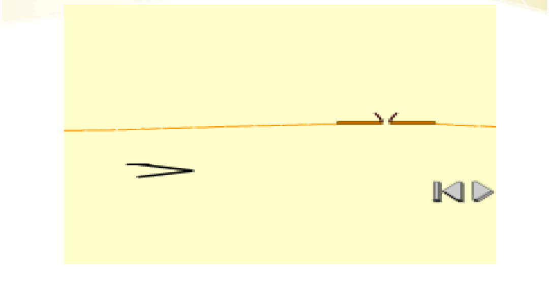
(5) Pantograph passage after the section has been raised
(6) Adjustment method for raising the section
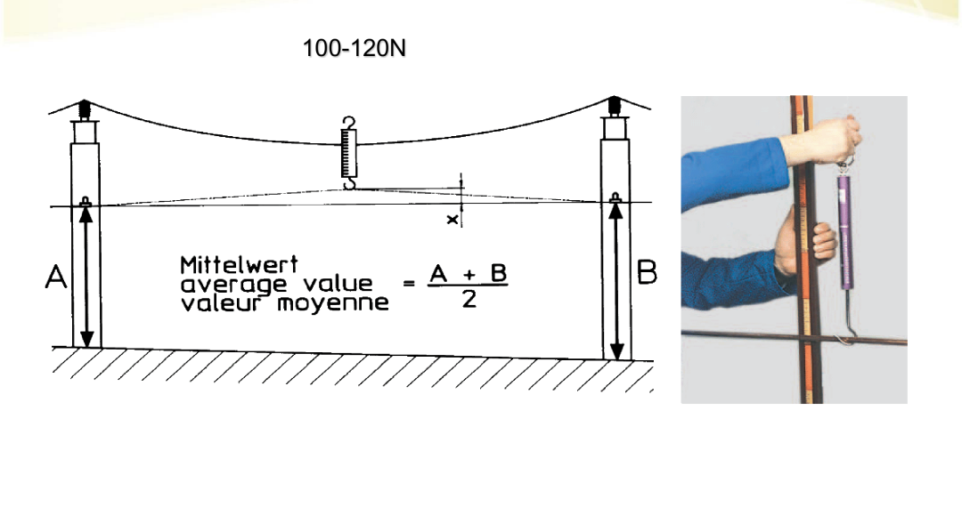
Apply an upward pull of 100~120 N with a spring balance and measure the displacement "x" at that point, so as to ensure that the section height meets the average value required by the formula (A + B) / 2.
6. Emergency Repair Principles and Plans for Section Insulators
6.1 General Emergency Repair Principle
6.2 Overall Classification of Emergency Repairs
| Category | Repair requirement | Treatment |
|---|---|---|
| Section insulators on the main line | Power supply and train operation must be restored as quickly as possible | Replace the section insulator as the situation allows; or, where the wires at both ends are badly damaged, temporarily bridge the gap with a length of contact wire |
| Other section insulators (crossover tracks, station tracks, etc.) | Restore power supply first so that main line operation is ensured | Carry out thorough repair after the last train of the day (end of revenue service) |
6.3 Emergency Repair of Section Insulators on Crossover / Stabling / Station Tracks
| Item | Details |
|---|---|
| 1. Repair principle | Restore traffic first, repair afterwards; restore one track first |
| 2. Anticipated objects | Section insulators on crossover tracks, stabling tracks, station tracks and the like |
| 3. Aims of the repair | Targeted temporary repair: restore power supply to the feeding section in which the section insulator is located first, so as to ensure traffic safety and reduce operating losses |
| 4. Analysis of the field situation | After the section insulator has come off, the contact wires at both ends drop to the ground and short-circuit, the wires are severely burnt, and the section insulator is damaged beyond further use |
| 5. Traffic requirements on site | Operation on the crossover track in which the section insulator is located may be suspended temporarily in order to restore main line operation |
| 6. Repair measures | Deal with the crossover first at the point of the broken wire; once the suspension is clear of the ground, suspend crossover traffic, and restore main line operation after energising |
Emergency repair steps for a crossover
- Implement the safety measures for voltage verification and earthing and for traffic protection in the repair zone, and open the disconnectors that reduce the extent of the repair zone.
- Unload the balance weights with a chain hoist at the wire anchor point; once unloading is complete, lash the chain hoist with iron wire.
- Pull up the broken wire with a tensioning tool at the point of the break, and then lash the contact wire and the messenger wire together with iron wire.
- Remove the limit tube of the wire crossing adjacent to the section insulator and raise the crossover contact wire to a certain height, so that the pantograph of a train passing on the main line cannot catch on it.
- Check the technical parameters of the main line OCS to confirm that they meet the conditions for safe train operation.
- Close the disconnectors, open the main line to traffic first, and block the crossover track to all traffic.
1. Strictly observe the voltage verification and earthing procedure, and keep to the safety clearance from live lines during the work.
2. After the repair, no tool and no temporarily used material or part may intrude into the vehicle clearance gauge.
3. After the repair, personnel must remain on site to observe current collection by passing trains and ensure traffic safety.
6.4 Emergency Repair Plan for Section Insulators on the Main Line
| Item | Details |
|---|---|
| 1. Repair principle | Restore traffic first, repair afterwards; restore one track first |
| 2. Anticipated objects | Section insulators at critical positions on the main line along the whole line (for example up and down line sectioning, station sectioning) |
| 3. Aims of the repair | Restore power supply and meet the requirements of train operation |
| 4. Analysis of the field situation | Case 1: the section insulator is damaged, has not come off and the wires are undamaged. Case 2: the section insulator has come off, the contact wires at both ends drop to the ground and short-circuit, and the wires are severely burnt. |
| 5. Traffic requirements on site | Restore main line power supply and operation in the shortest possible time |
| 6. Repair measures | Case 1: replace the damaged section insulator. Case 2: splice in a length of contact wire at the point of the break and then restore operation. |
Emergency repair steps for the main line
- Implement the safety measures for voltage verification and earthing and for traffic protection in the repair zone.
- As the situation requires, unload the balance weights with a chain hoist at the wire anchor point.
- Proceed according to the two cases: Case 1 - install tensioning tools on both sides of the section insulator and replace the damaged section insulator; Case 2 - pull up the broken wire with a tensioning tool, prepare the broken ends and splice in a new length of contact wire.
- Restore the tension load of the balance weights.
- Follow-up work for the two cases of step 3: Case 1 - adjust the section insulator so that it meets the operating conditions; Case 2 - install droppers on the new wire for suspension, ensuring that the contact wire height and gradient allow safe passage; where necessary, bridge the messenger wire section insulator.
- Check the wire crossings adjacent to the section insulator and the contact suspension of the half tensioning section for any other abnormality; if none is found, traffic may be restored first.
1. Before repairing, always check the condition of the equipment in the half tensioning section and at the mid-point anchor.
2. If, after splicing, the technical parameters at the wire crossing have changed and traffic cannot be restored temporarily, it is recommended to remove the limit tube of the wire crossing and raise the side track to a certain height so that the main line can be opened to traffic first.
3. After the repair, personnel must remain on site to observe current collection by passing trains and ensure traffic safety.
4. After the repair, no tool and no temporarily used material or part may intrude into the vehicle clearance gauge.
5. Strictly observe the voltage verification and earthing procedure, and keep to the safety clearance from live lines during the work.
7. Quick Reference of Key Parameters
To learn more about the models, parameters and selection options of our section insulator products, or to obtain an OCS electrical sectioning solution tailored to your line conditions, please visit our contact page for technical support.