Abstract
OCS spare parts come in a great many varieties and complex specifications, yet every part has a unique identity card: its part code. This article explains, by the four categories of masts, insulators, conductors and fittings, how the codes of common OCS parts are constructed. It starts from the five origins of the letters and the meaning of the numbers, and then reads off, item by item, the H78/8.7+3 cranked-web mast and the GQ80/9+3 equal-diameter circular mast, the G-series steel masts, the letter structure of the XP/XWP/LXP suspension insulators and of the QXN/QBN/QBZ rod and pin insulators, the meaning of the numbers in the GLCA/GLCB and CT/CTH contact wires and in GJ, GTJ, LBGJ, LGJ and other stranded wires, and how to read the three part-numbering systems JL16(60)-89, TB2075.15-90 and JHJL67-2004(S). The article ends with tables that distinguish easily confused parts such as Y-type and W-type double-eye connectors, the W-7A and WS-7A ball-eye plates, the four kinds of rod and the JB and B series parallel-groove clamps, together with a four-step reading method, for quick reference by designers, buyers, erection inspectors and maintenance staff.
Keywords: OCS spare parts; part code; mast type; insulator type; contact wire type; steel stranded wire; JL16; TB2075; ball-eye plate; parallel-groove clamp
I. Letters Name, Numbers Quantify: General Rules of the Code
The OCS is a special transmission line erected above the railway and delivering electrical energy to electric locomotives. Along the whole line it is made up of masts, insulators, the contact suspension and thousands of connecting parts, and the same kind of part is usually divided into several specifications by capacity, height, load or cross-section. So that every part can be identified unambiguously in design drawings, material schedules, erection requisitions and maintenance records, the industry has laid down a uniform code for each part: a part code is normally made up of letters and numbers. The letters answer "what part is this", the numbers answer "what are its main parameters".
1. Meaning of the letters
The letters in a part code come from five main sources:
| No. | Source of the letter | Rule | Typical example |
|---|---|---|---|
| 1 | Initial letter of the Chinese pinyin | Take the first letter of the pinyin of the part name | G (steel mast), T (copper), JL (OCS part) |
| 2 | Initial letter of an English word | Take the first letter of the English word | Some imported types of clamp |
| 3 | Serial letter | Where a product has several specifications they are denoted A, B, C, D, E | GLCA and GLCB, the two steel-aluminium contact wires |
| 4 | Pictographic letter | Letters whose shape resembles the profile or cross-section of the part | H-section steel mast, V-type connecting plate |
| 5 | Composite formation | Pinyin letters and English letters combined | GQ (high strength), GLC (steel-aluminium contact wire) |
2. Meaning of the numbers
The numbers are generally the main parameters of the part; which parameter they represent depends on the class of part:
| Meaning of the number | Applies to | Usual unit |
|---|---|---|
| Effective length | Bar-type parts | mm |
| Hole spacing | Anchor steel parts | mm |
| Nominal cross-sectional area | All types of conductor | mm² |
| Rated voltage | Insulator class | kV |
| Mechanical failing load | Suspension insulators | kN |
| Capacity (moment) | Mast class | kN·m |
| Design serial number / year of design or approval | All classes of part | — |
Related products: Support and positioning assembly · Positioning device · Connection fasteners
II. Reading Mast Codes
OCS masts belong mainly to two families: reinforced concrete masts and steel masts. Reinforced concrete masts are nowadays mostly of two forms, the cranked-web mast and the equal-diameter circular mast; steel masts, depending on where they are installed, take several profile forms such as the lattice type (ordinary steel mast), the circular type, the H-section type, the hexagonal type and the polygonal type.
1. Reinforced concrete masts: cranked-web H and equal-diameter GQ
The cranked-web mast is coded for example H78/8.7+3, and the equal-diameter circular mast (also called the high-strength equal-diameter prestressed reinforced concrete mast) for example GQ80/9+3. The codes break down as follows:
| Code element | Meaning | Example value | Unit |
|---|---|---|---|
| H | Reinforced concrete mast | — | — |
| GQ | High-strength mast (pinyin abbreviation of "gao qiang", high strength) | — | — |
| Numerator | Moment the mast can withstand perpendicular to the track (mast capacity) | 78 / 80 | kN·m |
| First part of the denominator | Height of the mast above ground | 8.7 / 9 | m |
| " + n" part of the denominator | Depth to which the mast is buried | +3 / +3 | m |
Note: if the numerator consists of two numbers, the first is the moment the mast can withstand perpendicular to the track and the second the moment it can withstand along the track.
2. Steel masts: the G series and its derivatives
An ordinary steel mast is coded for example G250/13: G denotes a steel mast, 250 is the capacity of the mast perpendicular to the track (kN·m) and 13 the height of the mast itself (m). Adding different suffixes after the initial G produces specialised steel masts for various duties and shapes:
| Code example | Name | Characteristic |
|---|---|---|
| G250/13 | Ordinary steel mast (lattice type) | Basic type; 250 is the capacity in kN·m and 13 the mast height in m |
| Gs250/13 | Double-track cantilever steel mast | Carries the cantilever loads of the up and the down track at the same time |
| Gf250/13 | Splayed-leg anchor steel mast | Used for anchoring conductors at overlap joints |
| Gx250/13 | Inclined-leg steel mast | Inclined-leg structure, occupies less ground |
| Gz250/13 | Narrow steel mast | Narrow-section structure |
| Gy250/13 | Circular steel mast | Circular cross-section |
Related products: Masts and foundations · Bracket system
III. Reading Insulator Codes
Insulators perform the double duty of electrical insulation and mechanical connection. The common structural forms fall into three families, the suspension, rod and pin types, alongside newer composite products such as silicone-rubber, epoxy-resin and synthetic insulators.
1. Suspension insulators: XP / XWP / LXP
| Type | Class | Breakdown of the code |
|---|---|---|
| XP-70 | Ball-and-socket suspension · ordinary | X = suspension insulator, P = ordinary, 70 = mechanical failing load (kN) |
| XWP2-70 | Ball-and-socket suspension · anti-fouling | W (initial of the pinyin "wu", pollution) inserted between X and P gives the anti-fouling type; 2 = heavy anti-fouling |
| XP-70T | Clevis-cap suspension · ordinary | The final T denotes a clevis-cap suspension insulator |
| XWP2-70T | Clevis-cap suspension · anti-fouling | Anti-fouling W, heavy-pollution grade 2 and clevis T combined |
| LXP-70 | Toughened-glass suspension insulator | L indicates toughened glass |
Key point: "T" denotes a clevis-cap suspension insulator and is precisely what distinguishes the clevis-cap type from the ball-and-socket type; the connection mode of the ball-and-socket type is not shown in the code.
2. Rod insulators: the QXN / QBN / QBZ series
The main types are QXN1-25, QXN1-25A, QXN2-25, QXN2-25A, QBN1-25D, QBN1-25, QBN2-25D, QBN2-25, QBZ1-25D, QBZ1-25, QBZ2-25D and QBZ2-25, twelve in all. The meaning of the letters and symbols is as follows:
| Symbol | Meaning | Symbol | Meaning |
|---|---|---|---|
| Q | Electrified railway | Z | Double-insulation type (S is also used for double insulation) |
| X | Suspension type | 1 | Light-pollution type |
| B | For cantilever assembly | 2 | Heavy-pollution type |
| N | Pollution-resistant type | 25 | Rated voltage 25 kV |
| A | Rod insulator for tunnels (type A) | D | Large-diameter type for 2-inch cantilever tubes, as distinct from the 1½-inch bore |
Difference in end construction: both ends of a suspension rod insulator are eye holes; a cantilever rod insulator has a single-eye single-hole end at one end and a tube end for connection to the cantilever tube at the other. The suspension type is further divided into the ordinary type, with a single-eye single-hole end at both ends, and the A type, with a single-eye single-hole end at one end and a single-eye double-hole end at the other.
3. Pin insulators: P-10T and its suffixes
A common type is P-10T: P denotes the ordinary type, 10 the withstand voltage class of 10 kV, and the final letter the combination of pin shape and crossarm material:
| Final letter | Meaning |
|---|---|
| T | Straight pin for an iron crossarm |
| M | Straight pin for a wooden crossarm (tapered wood thread, screwed directly into the wooden crossarm) |
| W | Bent pin |
The final letter therefore carries two pieces of information at once: whether the pin is straight or bent, and whether the crossarm is of iron or of wood.
On composite insulators: silicone-rubber, epoxy-resin and synthetic (composite) insulators have been increasingly used on new lines in recent years. They are built from a silicone rubber shed over a fibre-reinforced core rod and offer low weight, good resistance to pollution flashover and long cleaning-free intervals. The coding of these products is not yet fully harmonised with that of conventional porcelain and glass insulators, so when selecting them the manufacturer catalogue and the design documents should be consulted directly.
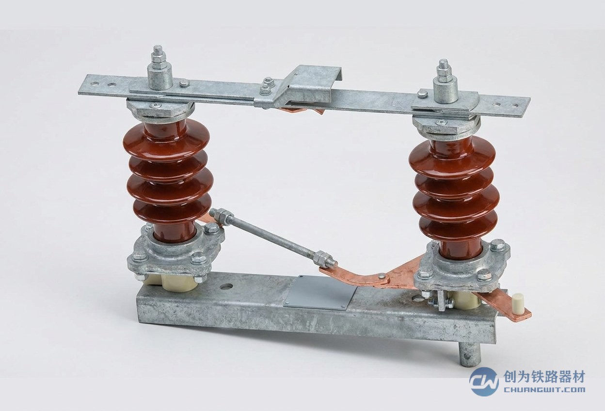
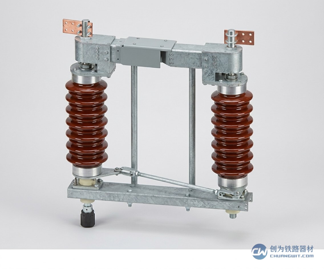
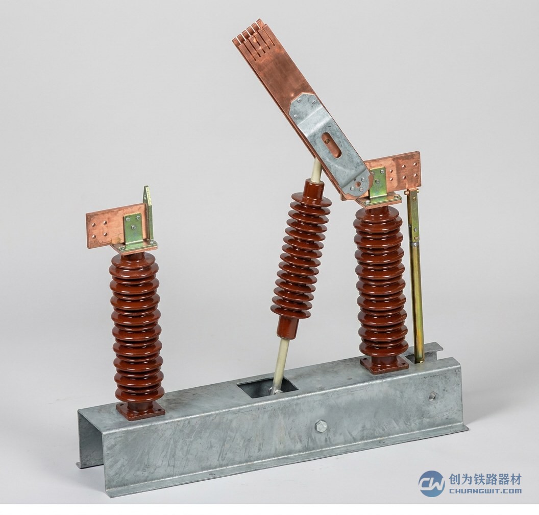
Related products: Insulator series · Phase-break insulator · Sectioning insulator · Disconnector
IV. Reading Conductor Codes
The cross-sectional area of every type of conductor used on the OCS is expressed in mm². By structure they fall into two families: the contact wire, the working conductor that the pantograph contact strip rubs against, and the stranded wire, made by stranding several single wires and used as messenger wire, auxiliary conductor, electrical connection, stay wire, dropper, diagonal hanger wire and compensation rope.
1. Contact wire: steel-aluminium GLCA/GLCB, pure copper CT, copper alloy CTH
Steel-aluminium contact wire comes in two types, GLCA-100/215 and GLCB-80/173: GLC denotes steel-aluminium contact wire and A and B the two specifications. The denominator is the total cross-sectional area of the wire and the numerator the area of copper contact wire to which its conductivity is equivalent. For example GLCA-100/215 is a type A steel-aluminium contact wire with a copper equivalent of 100 mm² and a total cross-section of 215 mm².
Pure copper contact wire types include CT-70 and CT-110: C stands for tram wire or contact wire, T for copper (pinyin abbreviation) and the following number is the nominal cross-sectional area.
Copper alloy contact wire adds H after CT to denote an alloy and then A, L, M or S according to the alloying element:
| Suffix | Alloy | Typical type |
|---|---|---|
| A | Copper-silver alloy | CTHA-120 |
| L | Copper-magnesium alloy (magnesium 0.2%) | CTHL-120 |
| M | Copper-magnesium alloy (magnesium 0.5%) | CTHM-120 |
| S | Copper-tin alloy (commonly called bronze) | CTHS-120 |
2. Stranded wires: quick reference to ten common codes
| Code | Name | Meaning of the numbers and special notation | Typical types |
|---|---|---|---|
| GJ | Steel stranded wire | "GJ" is the pinyin abbreviation of "gang jiao" (steel strand); the number is the nominal cross-sectional area in mm² | GJ-50, GJ-70, GJ-80, GJ-100 |
| LXGJ | Aluminium-zinc coated steel stranded wire | Pinyin abbreviation of "lü xin gang jiao"; the number is the cross-sectional area | LXGJ-100 |
| GTJ | Copper-clad steel stranded wire | GTJ-100 has a total cross-section of 100 mm²; GTJ-80/40(19/7) has a copper section of 80 and a steel section of 40 mm², with 19 strands in all of which 7 are copper-clad | GTJ-100, GTJ-80/40(19/7) |
| LBGJ | Aluminium-clad steel stranded wire | Pinyin abbreviation of "lü bao gang jiao"; the number is the total cross-sectional area and the bracket gives the number of strands | LBGJ-70(19) |
| TJ | Hard-drawn copper stranded wire | Pinyin abbreviation of "tong jiao"; the number is the nominal cross-sectional area | TJ-70 |
| THJ | Hard-drawn copper alloy stranded wire | H = alloy; the suffixes A/L/M/S mean the same as in the contact wire series | THJL-95 (95 mm² hard-drawn copper-magnesium alloy stranded wire with 0.2% magnesium) |
| TJR | Annealed copper stranded wire | R is the pinyin initial of "ruan" (soft); used mainly as electrical connection jumper and dropper wire | TJR-16, TJR-25, TJR-35 |
| LJ | Aluminium stranded wire | Pinyin abbreviation of "lü jiao"; the number is the nominal cross-sectional area | LJ-70 |
| LGJ | Aluminium conductor steel-reinforced | LGJ denotes aluminium conductor steel-reinforced; the number is the nominal cross-sectional area | LGJ-70, LGJ-185 |
| LBGLJ | Aluminium-clad steel-core aluminium stranded wire | LBGLJ70/10(6/1): aluminium section 70 and aluminium-clad steel section 10 mm², with 6 aluminium wires and 1 aluminium-clad steel wire | LBGLJ70/10(6/1) |
Memory aid: the suffixes A/L/M/S of the THJ series denote exactly the same alloys and contents as the CTH contact wire series, so the two series can be memorised together. Whether a wire is hard or soft is shown by the presence of R: annealed copper stranded wire (TJR) is used mainly as electrical connection and dropper wire, as distinct from the hard-drawn copper stranded wire (TJ) used for messenger wires and the like.
Related products: Contact suspension · Electrical connection · Compensation device · Centre anchor
V. Reading Fitting Codes
Fittings are the most numerous parts and the most frequently updated. Their codes involve material designations and three parallel numbering systems: sequential numbering, standard numbering and engineering drawing numbering. When reading a code, first establish which system it comes from.
1. Codes by manufacturing material
| Material class | Code example | Explanation |
|---|---|---|
| ZHAC67-2.5 | Cast brass part | Grade of a cast brass alloy; the numbers are the composition characteristic values |
| KT38-8 | Malleable cast iron part | KT is the malleable iron designation; the numbers give the strength and elongation grades |
| HT15-33 | Grey cast iron part | HT is the grey iron designation; the numbers are the strength grade values |
| A3 → Q235A | Ordinary carbon steel part | The old grade A3 has been superseded by the current designation Q235A |
| — | Stainless steel part | Marked with the specific stainless-steel grade |
2. Sequential numbering system: the JL series
The notation obtained by numbering OCS parts in sequence, as JL16-89 is the code of the sleeve thimble:
| Code element | Meaning |
|---|---|
| JL | OCS part (pinyin abbreviation) |
| 16 | Part serial number |
| Bracket ( … ) | Different versions of the same type of part are written after the serial number in brackets: originally the inch size was marked, so the 1½-inch sleeve thimble was written JL16(1½)-89 and the 2-inch version JL16(2)-89; the marking is now unified in millimetres, i.e. JL16(60)-89, where 60 is the size in mm of the cantilever tube it fits |
| 89 | Year of design (1989) |
3. Standard numbering system: the TB2075 series
The standard designation of OCS parts is TB2075. For example the standard designation of the sleeve thimble is TB2075.15-90: TB2075 denotes a railway-standard OCS part (2075 being the number of OCS parts in the railway standard), 15 is the part serial number and 90 the year of approval.
4. Engineering drawing numbering system: the JHJL example from the Beijing-Shanghai drawings
JHJL67-2004(S) denotes the single-cantilever upper base for a cranked-web concrete mast; it breaks down as follows:
| Code element | Meaning |
|---|---|
| JH | Beijing-Shanghai line |
| JL | OCS part |
| 67 | Part number |
| 2004 | Year of design |
| Letter in brackets | Mast type and position for which the part is intended: S = upper base, X = lower base |
Base parts are further distinguished by suffix letters for mast form and position:
| Suffix | Mast | Position of the base |
|---|---|---|
| ys | Equal-diameter circular mast | Single-cantilever upper base |
| yss | Equal-diameter circular mast | Double-cantilever upper base |
| yx | Equal-diameter circular mast | Cantilever lower base |
| ysx | Equal-diameter circular mast | Double-cantilever lower base |
| gs / gss / gx / gsx | Steel mast | The four positions listed above |
Related products: Connection fasteners · Support and positioning assembly · Masts and foundations
VI. Telling Easily Confused Parts Apart
1. Double-eye connectors: Y type and W type
Y means with and W means without, that is, whether or not a pin is present. One end of every double-eye connector carries a bolt pin: if the other end also carries a pin the part is the Y type, if not it is the W type. The letters Y and W on right-angle suspension plates mean the same thing.
2. Ball-eye plates: W-7A / W-7B / WS-7A
W denotes a ball-eye plate and S that the other end is a double clevis; "7" means a failing tension of 7 tonnes (note that the mechanical units formerly used were the kilogram and the tonne); the following A and B are design serial numbers denoting two different versions:
| Type | Construction | Failing tension | Effective length |
|---|---|---|---|
| W-7A | Ball-eye plate, other end not a double clevis | about 7 t | about 60 mm |
| W-7B | Ball-eye plate, other end not a double clevis | about 7 t | about 100 mm |
| WS-7A | Ball-eye plate with a double clevis at the other end | about 7 t | about 60 mm |
3. The various rods: four types by end form
The ends of a rod are generally of three forms: spade, eye and thread. Common rods are divided into four types by the connection form at the two ends:
| Name | One end | Other end |
|---|---|---|
| Spade-eye rod | Spade end | Eye end |
| Double-eye rod | Eye end | Eye end |
| Spade-end rod | Spade end | Threaded end |
| Eye-end rod | Eye end | Threaded end |
4. Parallel-groove clamps: the aluminium clamp reserved for auxiliary conductors
"Parallel-groove clamp" refers specifically to the aluminium clamp used on auxiliary conductors. Other clamps of similar appearance have their own names and may not be called parallel-groove clamps: the earthing connection clamp is of iron and the messenger-wire electrical connection clamp is generally of copper. Parallel-groove clamps for OCS use come in equal-diameter and reducing versions:
| Type | Common types | Scope of application |
|---|---|---|
| Equal-diameter parallel-groove clamp | JB-1 ~ JB-4 | For joining two auxiliary conductors of the same cross-section; the four sizes serve LJ70, LJ120, LJ150, LJ185 and LJ240 aluminium or aluminium-conductor steel-reinforced wire respectively, the exact type being chosen at the design stage |
| Reducing parallel-groove clamp | B-31, B-32, B-41 | For joining two auxiliary conductors of different cross-section; B denotes a parallel-groove clamp and the two digits stand for the two conductor sizes: 1 = 70 mm², 2 = 120 mm², 3 = 150 mm², 4 = 185 or 240 mm². Thus B-31 joins LJ-150 to LJ-70 and B-32 joins LJ-150 to LJ-120 |
Note: the specific type must always be taken from the drawings.
VII. The Four-Step Reading Method and Advice on Checking a Selection
Bringing these rules together, any part code met in the field can be read quickly in four steps:
- Step 1 · Fix the broad class: the first letter identifies the part family, G/H/GQ for masts, X/Q for insulators, CT/TJ/LGJ for conductors and JL/TB for fittings.
- Step 2 · Break down the letters: read the middle letters segment by segment to identify the construction form (cantilever or suspension), the material (copper, steel, aluminium, alloy) and the protection level (anti-fouling, pollution-resistant, double insulation).
- Step 3 · Read the numbers: check the load-carrying capability against the main parameters, capacity (kN·m) and height above ground for masts, rated voltage (kV) and failing load (kN) for insulators, nominal cross-sectional area (mm²) for conductors.
- Step 4 · Check the version: confirm the year of design, the year of approval and the mating dimension in brackets, paying particular attention to differences between old and new standards such as inch to millimetre, A3 to Q235A and Z to S, and check every item against the design drawings.
Advice for purchasing and acceptance:
- The types quoted in this article are typical examples; the specification actually supplied must follow the approved design documents and the technical standards in force.
- The same serial number may exist in several size versions (for instance the 1½-inch, 2-inch and 60 mm markings of the JL16 series), so the mating dimension with the existing cantilever tube must be confirmed before ordering.
- Quick field discrimination of easily confused parts: for a double-eye connector, check whether the other end carries a pin to decide Y or W; for a ball-eye plate, measure the effective length to decide A or B; for a rod, match the two ends to the table.
- Parallel-groove clamps must be distinguished by material and purpose: the aluminium clamp is used only on auxiliary conductors, and the earthing connection clamp (iron) and the messenger-wire electrical connection clamp (copper) must not be interchanged.
Disclaimer: this article has been compiled from general technical material on railway overhead contact systems and is intended for study, exchange and quick reference only. The specific parameters of each type are governed by the standards in force, the design documents and the manufacturer catalogues issued by the competent authority.
Further reading: Illustrated inspection guide for OCS components (all 16 classes) · Metro OCS component identification atlas · OCS fundamentals explained in 112 slides · Complete technical analysis of sectioning insulators · Fully compensated catenary suspension under AT feeding