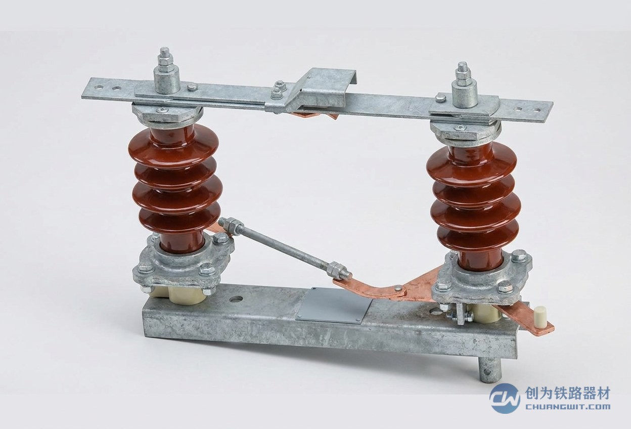
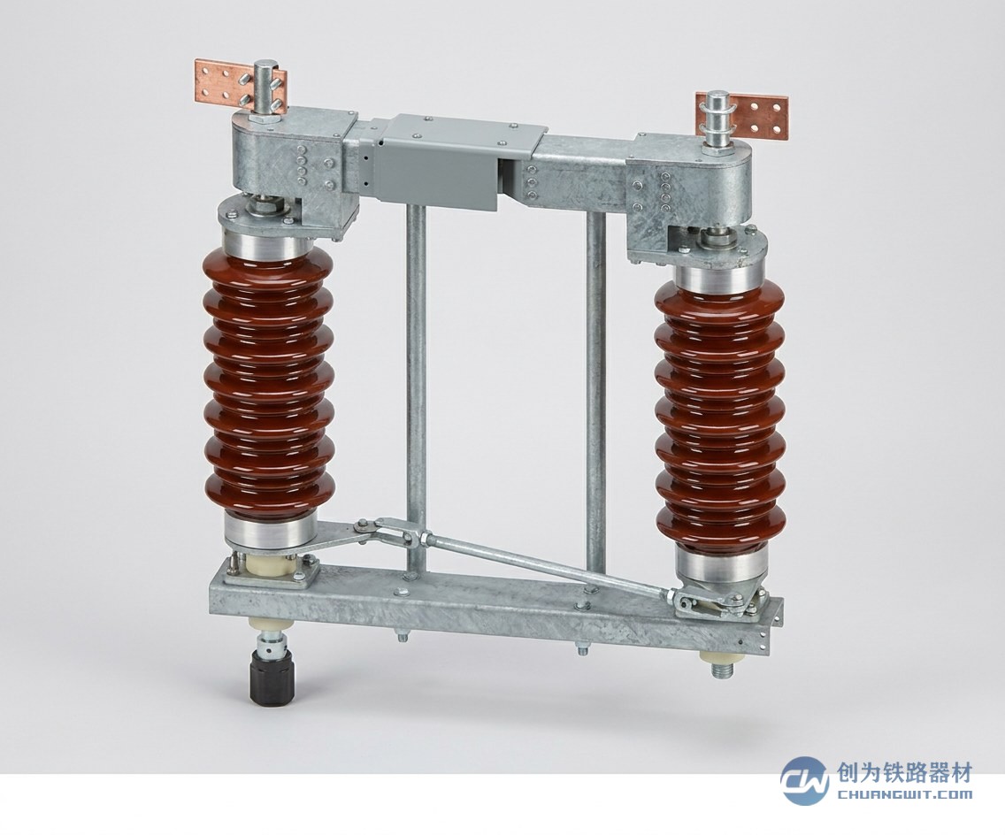
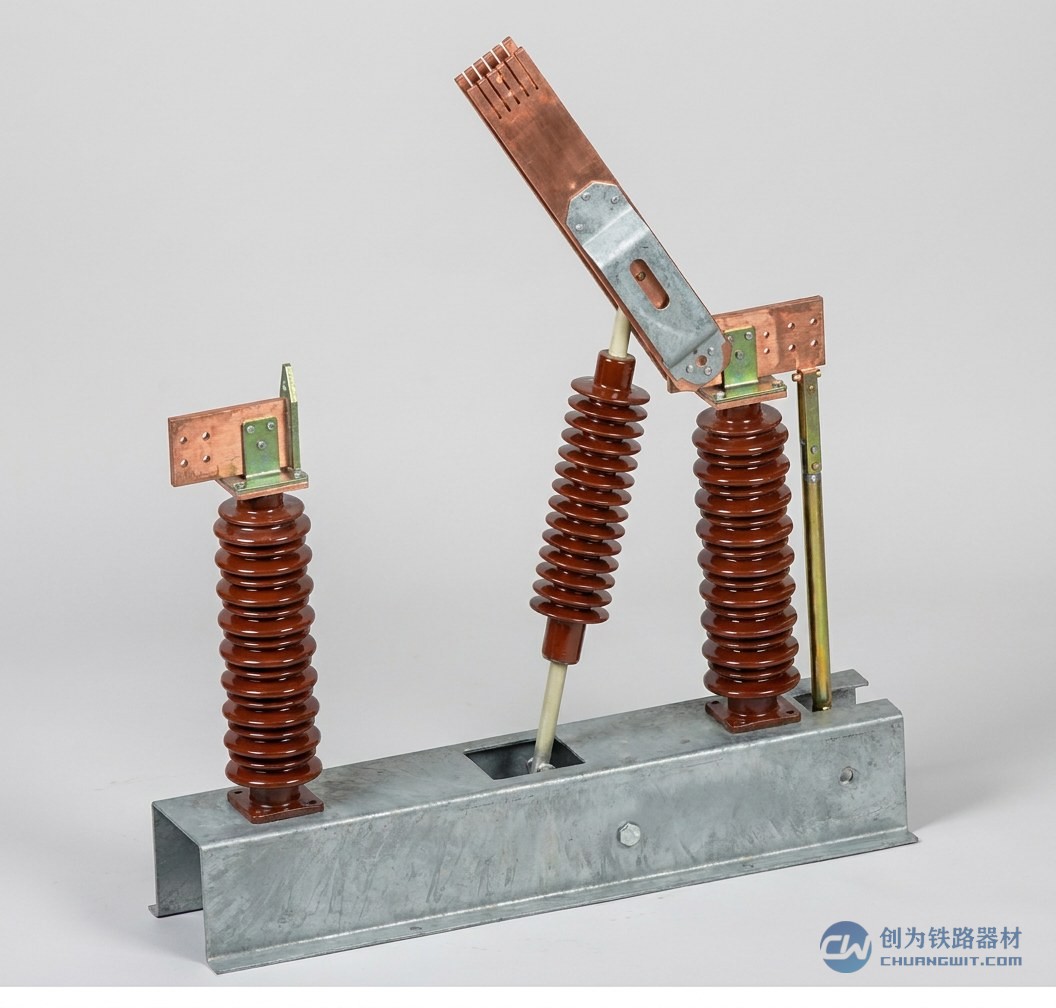
In the overhead contact systems of electrified railways and urban rail transit, the section insulator is a small component that nonetheless directly determines power supply reliability. It is connected in series in the middle of the contact wire or busbar, dividing the otherwise continuously energised overhead contact system into electrically isolated sections, and thereby creating the basic conditions for power supply section management, de-energised maintenance and fault isolation. Readers who are getting to know overhead contact systems often ask: what does a section insulator actually do, and how does it work? This article addresses the function and working principle of OCS section insulators, covering both mainline railway and urban rail applications, and is intended as a reference for power supply designers, installation contractors and O&M personnel.
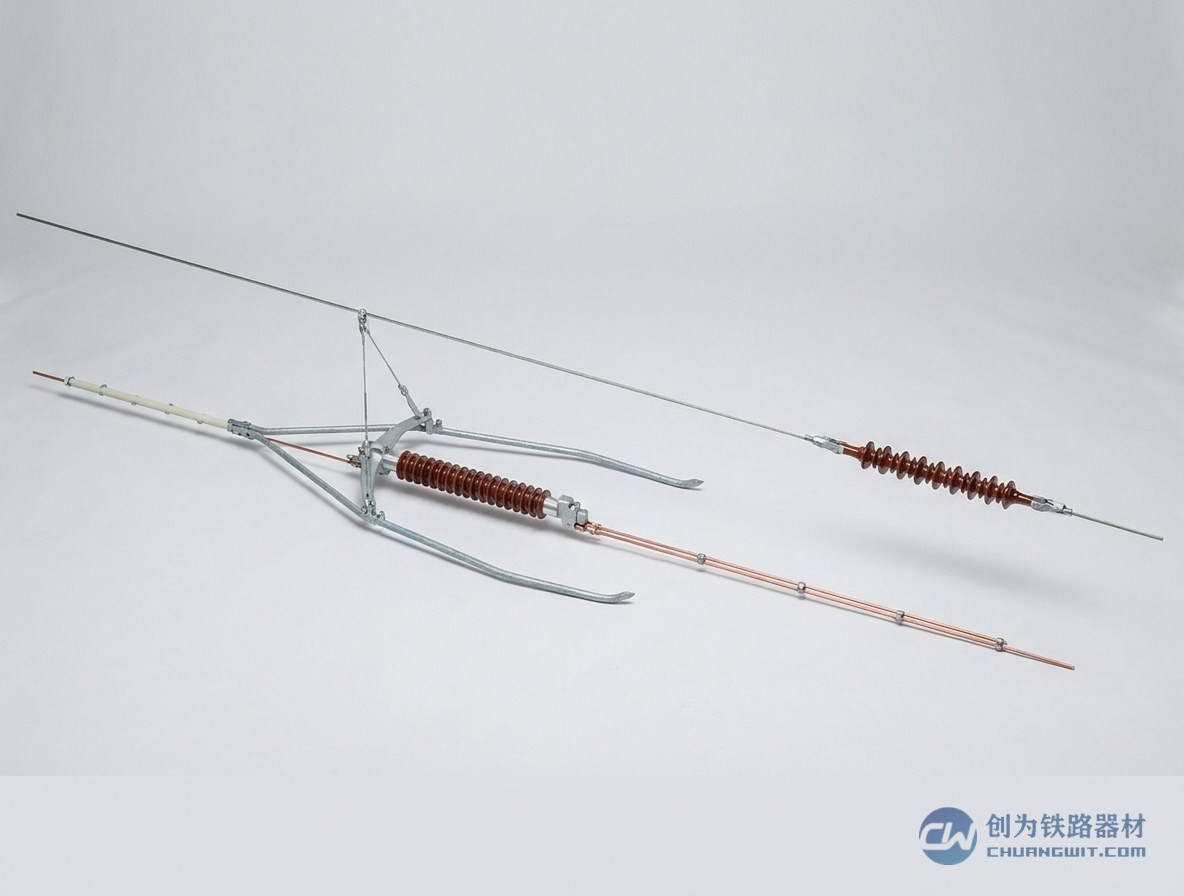
Why Does an OCS Need Electrical Sectioning?
The overhead contact system is erected continuously along the line, yet from the standpoint of power supply and operating organisation it cannot always run energised as a single entity. There are three main reasons for this.
The first is the need for power supply sections. The capacity of a traction substation is limited, so a line is normally divided into a number of feeding arms and power supply sections, each fed by its own feeder. Only by separating the overhead contact system electrically can adjacent sections remain independent of one another, and only then can feeder protection operate correctly and clear faults precisely.
The second is the need for de-energised maintenance. Overhead contact systems require periodic inspection, cleaning and component replacement, and this work must be carried out with the supply switched off. By combining section insulators with disconnectors, only the track or section to be maintained needs to be isolated while adjacent lines continue to operate, keeping the impact of possession work on traffic organisation to a minimum.
The third is the need for fault isolation. When a fault occurs on the overhead contact system or on a train, or when a foreign object intrudes into the clearance gauge, a sectioned layout confines the consequences to one section, preventing the whole feeder or even the entire station area from being de-energised, and making it easier to locate the fault, organise repairs and restore supply quickly.
It is fair to say that electrical sectioning is the foundation that makes an overhead contact system controllable, manageable and maintainable, and the section insulator is one of the components most commonly used to achieve it.
What Does an OCS Section Insulator Do?
The function of a section insulator can be summarised as mechanically continuous, electrically isolated: both ends are reliably connected to the contact wire (or busbar) and can withstand the OCS tension and the sliding current collection of the pantograph, while the insulating element in the middle separates the wires on either side electrically, so that the two sides become sections that can be switched on and off independently. Specifically, this covers:
- Dividing power supply sections: together with substation feeders and disconnectors, it splits the overhead contact system into electrically independent supply units;
- Supporting de-energised maintenance: the track to be maintained is simply isolated at the sectioning point, without affecting traffic on adjacent lines;
- Providing fault isolation: in the event of a fault the de-energised area is reduced and the time needed to locate the fault and restore supply is shortened;
- Separating dedicated lines: depot lines, loading lines and preparation lines are electrically separated from the running lines so that they can be managed independently;
- Improving work safety: there is a definite electrical break between the de-energised section and the live section, reducing the risk of accidental energisation or contact.
It should be noted that the overhead contact system on both sides of a section insulator normally belongs to the same phase, i.e. it is a same-phase sectioning point. This differs functionally from the phase insulator used at AC phase breaks, and the two should be distinguished according to the design documents when they are specified.
How Does a Section Insulator Work?
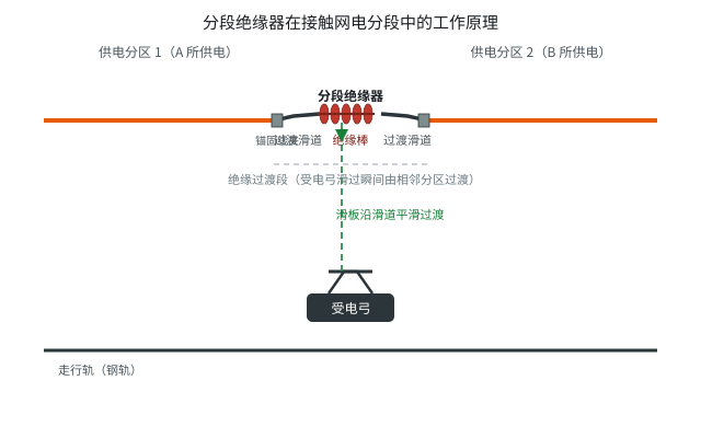
A section insulator consists of the main insulating element, the arc-quenching arrangement, the guide runners and the connecting fittings at both ends (the individual part names are covered in the FAQ below and in the dedicated structural article on this site). The key to understanding how a section insulator works is to look at how the pantograph passes across the insulating section.
At standstill, the insulating section separates the contact wires on either side, and the two power supply sections operate independently without affecting each other.
When an electric locomotive or an EMU approaches, the pantograph strip first contacts the guide runner on the entry side. The guide runner is a metal ramp that blends smoothly with the contact wires on both sides, providing the strip with a continuous transition path and preventing it from striking the insulating element directly. As the strip slides along the runner across the insulating section, on the common twin-strip pantograph the two strips successively contact the wires on either side and complete the crossing within a very short time, so current collection undergoes a brief interruption or changeover. This is what is usually described as a momentary loss of supply during the transition.
During the transition a short arc may occur between the strip and the runner. This is where the arc-quenching arrangement on the section insulator comes into play: it guides the arc to a dedicated protective area so that it is stretched and extinguished, preventing erosion of the insulating element surface and the ends of the runners.
For this reason, traction units are generally not permitted to stand at a section insulator while drawing current. They should be operated in accordance with the relevant traffic and power supply regulations when passing, so as to avoid prolonged arcing and damage to the components.
Where Are Section Insulators Normally Installed?
The installation positions of section insulators are determined by the OCS layout design. Typical locations include:
- Freight and loading lines: the line can be isolated on its own during loading or unloading operations without affecting work on other tracks in the station;
- Preparation lines and depot lines: at locomotive and rolling stock depots, so that de-energised work inside the shed can be managed separately from the supply outside;
- Yard and area boundaries: in large stations, where power supply sections are divided by yard or by work area, sectioning points are provided between them;
- Between up and down lines: the up and down overhead contact systems form separate sections so that faults and maintenance on one do not affect the other;
- Depot and stabling yard access lines: creating a clear electrical boundary between depot tracks and running lines.
When selecting locations, designers take into account the division of power supply sections, the arrangement of maintenance possessions, the position of disconnectors and the conditions for pantograph passage, so that the section insulator both satisfies the electrical isolation requirement and offers good sliding performance.
Application Differences Between 25kV Railway and DC1500V Urban Rail
Section insulators are found in systems of every type of traction supply, but the operating conditions on mainline railways and in urban rail transit differ markedly.
Electrified mainline railways use single-phase industrial-frequency AC supply with a nominal OCS voltage of 25kV. Train speeds are high and the dynamic interaction between pantograph and catenary is intense, so the section insulator must guarantee both insulation margin and smooth running under high voltage and high speed.
Urban rail transit generally uses DC1500V supply. Although the voltage level is lower, headways are short and trains start and stop frequently, and the installation space inside tunnels is restricted. In addition to flexible suspension, rigid suspension is widely used, so section insulators have to be designed specifically for different suspension forms and installation interfaces.
The section insulator range from Henan Chuangwit Railway Equipment Co., Ltd. covers both applications: the FYFH series for 25kV railway applications complies with TB/T 3036-2016; for DC1500V urban rail systems there are types such as FYFH-0.6T-DC for rigid suspension and 1.0TG and 2.0TG for flexible suspension, complying with TB/T 3252-2022 and suitable for speeds up to 120km/h. The two product families differ in insulation level, structural form and mounting method, and should be selected according to the traction system and suspension type of the line.
Frequently Asked Questions
What is the difference between a section insulator and a phase insulator?
A section insulator provides same-phase sectioning: the overhead contact systems on both sides are at the same phase and the same potential, and it is mainly used for electrical isolation between tracks and between power supply sections. A phase insulator is used at AC phase breaks, where the two sides belong to feeding arms of different phases, and the traction unit must be operated according to the requirements for passing a phase break. The two look similar but perform different functions and must not be interchanged.
What are the individual parts of a section insulator called?
A typical section insulator consists of the main insulating element (composite insulating rod or insulator), the arc-quenching arrangement (arcing horns), the guide runners (transition ramps), and the anchoring clamps and connecting fittings at both ends. For the detailed structure and materials of each part, please refer to the illustrated structural article and the dedicated article on component names for section insulators on this site.
Does a train lose power momentarily when passing a section insulator?
It does undergo a brief interruption of supply. As the pantograph strip slides across the insulating section, current collection is interrupted or changed over for a very short time, and this is the normal working behaviour of a section insulator. Whether the supply must be switched off in advance, and how the train should be operated, is governed by the traffic organisation and power supply regulations of the individual line.
What are the consequences of contamination or damage to a section insulator?
Contamination and moisture on the surface of the insulating element can increase leakage current and even cause flashover, leading to an unintended connection between the two sections or a short circuit to earth. Wear of the guide runners and erosion of the arc-quenching arrangement by arcing will worsen the conditions for pantograph passage and accelerate arcing and component loss. The insulating parts should therefore be kept clean and dry, and the condition of the runners and arc-quenching parts should be inspected at regular intervals.
What checks are needed after replacing a section insulator?
Confirm that the type matches the traction system and suspension type of the line, check the height difference and smooth transition between the guide runners and the contact wires on both sides so that the pantograph can pass smoothly, and complete the acceptance and pre-energisation checks in accordance with the applicable procedures. Specific requirements are subject to the product technical documents and the design data.
Overall, the function of the section insulator runs through power supply sectioning, de-energised maintenance and fault isolation, making it an indispensable basic component of any overhead contact system. For further information on specifications and selection, please see the section insulator product range of Henan Chuangwit Railway Equipment Co., Ltd. If you are also interested in insulating devices for AC phase breaks, please refer to our introduction to the phase insulator, or contact us directly for technical support.