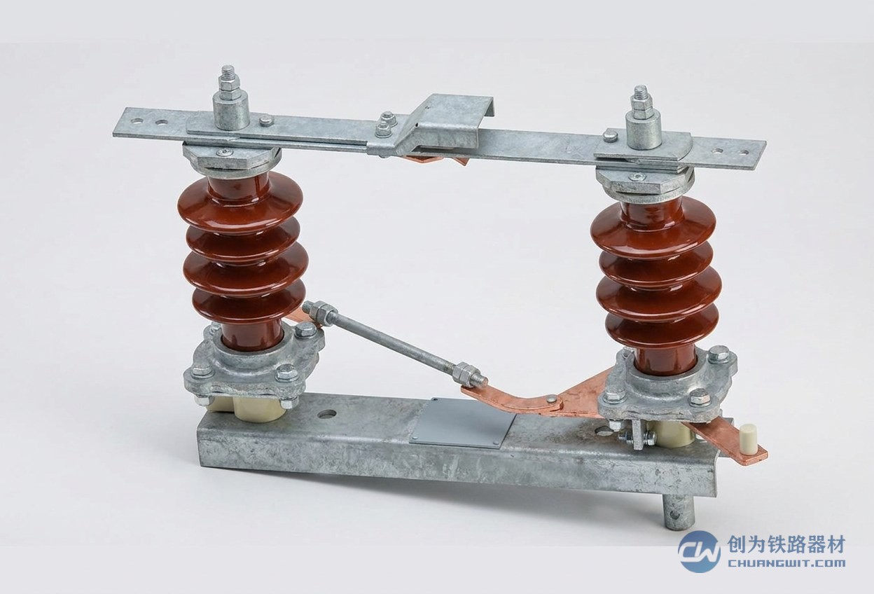
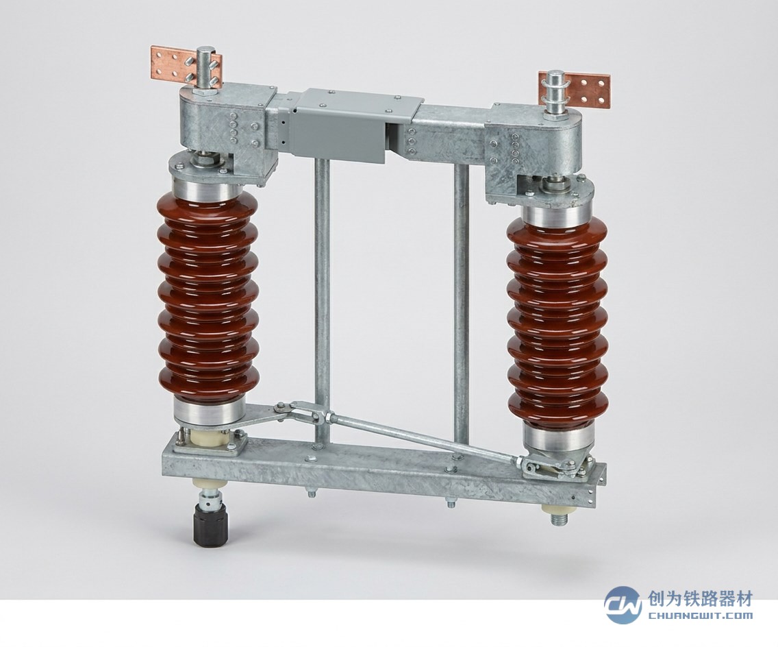
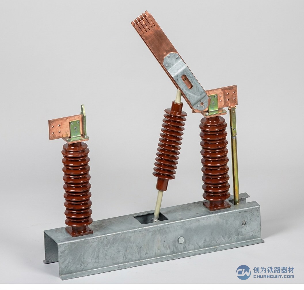
A section insulator is connected in series in the middle of the contact wire or busbar. It has to carry the OCS tension, keep the two sides reliably insulated, and let the pantograph slide across smoothly. These three tasks are shared among its individual parts. Following the actual construction, this article works through the components of a section insulator and the name of each part in an illustrated form, explaining one by one the function and usual material of the main insulating element, the arc-quenching arrangement, the guide runners and the end fittings, and comparing rigid and flexible suspension designs, so that readers can follow a detailed section insulator structure diagram.
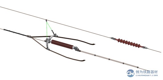
Components of a Section Insulator: List of Part Names
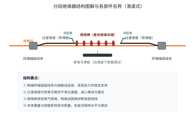
As a whole, the components of a section insulator can be grouped into four main parts:
- Main insulating element: the insulating rod or insulator, which is the core of both the insulation and the load bearing capacity of the whole unit;
- Arc-quenching arrangement: usually in the form of arcing horns or arcing rods, used to guide and extinguish the transition arc;
- Guide runners: also called transition ramps or runner bars, forming the path along which the pantograph crosses the insulating section;
- End anchoring clamps and fittings: connecting to the contact wire (or busbar) on both sides, transmitting tension and maintaining mechanical and electrical continuity.
In addition to these four groups, products from different manufacturers may be fitted with auxiliary parts such as connecting plates, adjustment plates and protective covers for installation adjustment and component protection. When reading a detailed section insulator structure diagram, grasp these four main lines first and then look at the detail differences between manufacturers, and confusion is unlikely.
Main Insulating Element: the Core of Insulation and Load Bearing
The main insulating element spans between the wires on either side and carries both the mechanical tensile load and the electrical isolation, making it the part of a section insulator with the most demanding operating requirements. Modern products generally use a composite insulating construction: an internal core rod carries the tensile load, an external shed and sheath with good hydrophobicity and pollution resistance covers it, and metal end fittings are provided at both ends for connection to the guide runners, clamps and other parts. Compared with conventional porcelain insulators, composite insulating elements are lighter and have better pollution flashover performance, adding only a small concentrated load to the overhead contact system, which helps to keep the pantograph-catenary relationship stable.
In day-to-day O&M the surface of the insulating element should be kept clean and dry. During patrols, check the sheds for damage, cracks and traces of electrical erosion, and deal with any problem promptly or replace the part, so as to prevent increased leakage current from causing flashover.
The Role of the Arc-Quenching Arrangement (Arcing Horns)
At the instant the pantograph crosses the insulating section, a short arc may be drawn between the strip and the runner. Without a dedicated protective structure, the arc could erode the surface of the insulating element directly, and the accumulated effect over time would degrade the insulation performance. The arc-quenching arrangement exists to solve this problem, most commonly in the form of a pair of arcing horns or arcing rods.
Its working logic is not complicated: making use of the tendency of an arc to develop along the shortest gap, it guides any arc that occurs to a dedicated arcing area so that the arc is stretched and extinguished as quickly as possible, thereby protecting the surface of the insulating element and the ends of the guide runners. After a period in service the tips of the arcing horns may show burn damage, so the degree of erosion and the condition of the gap should be watched during inspection, and the part replaced in good time once it falls outside the limits permitted by the product technical conditions.
Guide Runners and End Fittings
Guide Runners (Transition Ramps)
The guide runners are among the most visible parts of a section insulator and are also called transition ramps or runner bars. At the insulating section they blend smoothly with the contact wires on both sides to form a continuous sliding path, so that the pantograph strip does not have to strike the insulating element directly but instead slides steadily along the runner across the insulating section, completing the transition between the two sides. The runners have to conduct current, resist wear and keep friction low at the same time, and are therefore usually made of a metal material that combines electrical conductivity with wear resistance; some products also apply friction-reducing measures to the working surface in order to reduce pantograph strip wear and extend the inspection interval. As the part that rubs directly against the strip, the guide runner is a wearing component, and its condition is a key item in patrols and maintenance.
Anchoring Clamps and Fittings at Both Ends
The clamps and fittings at both ends of a section insulator are responsible for connecting it reliably into the overhead contact system: on the one hand they grip the contact wire or connect to the busbar and transmit the OCS tension, and on the other they maintain a continuous electrical path and control the contact resistance. The quality of the connection between clamp and conductor directly affects power supply reliability, so installation should follow the product technical documents, and in service the joint should be checked for looseness, displacement and signs of local overheating.
Structural Differences Between Rigid and Flexible Suspension
The same electrical sectioning function is implemented differently in flexible and in rigid suspension.
Flexible suspension is common on mainline railways and on some surface sections of urban rail systems. The contact wire is suspended from the messenger wire by droppers, and the section insulator is connected in series within the contact wire, sharing the tension with the conductor and forming part of the overall catenary arrangement, which places comparatively high demands on component strength and elastic matching.
Rigid suspension is mostly used in tunnel sections of urban rail systems, where the busbar is a rigid aluminium-alloy structure and the section insulator is mounted between consecutive busbar lengths. Here the main concerns are the mounting fit with the busbar and the smoothness of pantograph passage, and the unit is not subject to the tension conditions found in flexible suspension.
For this reason the two classes of section insulator are generally not simply interchangeable in structural form or installation interface. Taking the products of Henan Chuangwit Railway Equipment Co., Ltd. as an example: for DC1500V urban rail systems there is the FYFH-0.6T-DC type for rigid suspension as well as the 1.0TG and 2.0TG types for flexible suspension, complying with TB/T 3252-2022 and suitable for speeds up to 120km/h; for 25kV railway systems the FYFH series is used, complying with TB/T 3036-2016. When selecting, first confirm the traction system and suspension type of the line, then choose the corresponding product type.
Frequently Asked Questions
What are the main components of a section insulator?
A typical section insulator consists of four main groups: the main insulating element (composite insulating rod or insulator), the arc-quenching arrangement (arcing horns), the guide runners (transition ramps), and the anchoring clamps and fittings at both ends. Some products are also supplied with auxiliary parts such as connecting plates and protective covers.
Which section insulator parts are wearing components?
The guide runners, which rub directly against the pantograph strip, are the main wearing components, and the tips of the arcing horns also erode gradually as a result of arcing. The insulating element and the clamp bodies are not conventional wear parts, but damage, cracks or looseness still need to be dealt with promptly.
How much guide runner wear calls for replacement?
The criteria should be taken from the product technical conditions and the maintenance regulations. Generally speaking, when the guide runner shows pronounced wear grooves, local loss of material, deformation or looseness, or when abnormal sparking or hard-point impacts occur as the pantograph passes, an inspection and corrective action should be arranged, and the unit should not be left in service with the defect.
Where can a detailed section insulator structure diagram be obtained?
A detailed section insulator structure diagram is normally supplied with the product technical documents, and the detailed construction differs between manufacturers and between types. The illustrated description in this article gives the general arrangement of the four main groups; reading it alongside the drawings and technical conditions for a specific product makes it easier to follow the name and position of each part.
Can rigid and flexible suspension section insulators be interchanged?
Generally not. Rigid suspension products are designed around the busbar installation interface, while flexible suspension products are designed for contact wire tension conditions. Their structural forms, mounting methods and load conditions differ, so the type should be selected to match the suspension type of the line, in accordance with the design documents and the product technical conditions.
Understanding the name and function of each part of a section insulator is the basis for correct selection, installation and maintenance. To go deeper into individual components, you can read the itswe encyclopedia entries on insulating element materials, the arcing horn and the transition ramp. For product data and selection advice on section insulators, please contact Henan Chuangwit Railway Equipment Co., Ltd. for support.